
- Catalogs
- TWK-ELEKTRONIK GmbH
- Vibration sensor NVA system description

Vibration sensor NVA system description

Vibration sensor NVA system description
The document provides specifications for the NVA65-A552S-1-Bxx vibration sensor, designed for wind power plants. It features analogue output and a programming interface compatible with the CANopen DS 301 standard.
The sensor is robust and suitable for harsh environments, intended for integration into wind power plants to measure acceleration.
The sensor offers analogue outputs for real-time data monitoring, crucial for operational efficiency and safety in wind power applications.
Details on CANopen functionality include error behavior and profile definitions, covering process data objects (PDOs) and service data objects (SDOs) for network communication and data exchange.
This section outlines the CANopen profile, including PDO structure, mapping objects, and manufacturer-specific objects for synchronization and diagnostics. It describes objects like device type, error register, and manufacturer-specific parameters.
Diagnostic objects monitor the sensor's performance and operational status, providing information on alarms, supported warnings, and operating time.
A comprehensive table lists all objects with default values for configuration and troubleshooting.
The sensor system includes acceleration sensors, a controller unit, and multiple output interfaces, designed to withstand harsh environments with IP 69K and IP 67 protection ratings. It features a filter circuit for transient and surge protection.
The system measures dynamic accelerations and processes them through programmable filter units, customizable for sampling frequency and filter characteristics. Outputs include configurable alarms and warnings.
Analogue outputs reflect filter behavior, with settings for zero points and amplification factors adjustable via the CANopen interface.
The document details the CANopen communication protocol, including error handling and profile definitions, outlining emergency message structures and detectable error types.
Users can program parameters like filter settings, relay configurations, and amplification factors, with a comprehensive list of CANopen objects and functionalities provided.
Flow diagrams and tables illustrate system architecture, bit timing specifications, and object mappings, offering a visual representation of system operation.
PDOs represent filter outputs not connected to an analogue output, with data output in Intel format and specific byte allocations for filters 3 to 6.
Details various objects like device type, error register, and manufacturer-specific parameters, with functionalities for storing and restoring parameters.
Describes PDO structure and enablement, with specific transmission types for asynchronous and synchronous results.
Details coding for mapping objects with specified lengths for transmit PDOs.
Includes node ID and bit rate settings, effective after saving and reset.
Includes objects for programming filter characteristics, factory calibration, and analogue channel adjustments.
Includes resolution settings for axes and warning/alarm levels for filters.
Adjustable between 120 Hz and 800 Hz, allowing for filter pass range shifting.
Options include None, X axis, Y axis, and raw data for diagnostic purposes.
Expressed in acceleration (g), calculated using a specific formula, with options for momentary, peak, or RMS values.
Monitored for new peak registrations, with RMS values calculated at the filter's sampling rate.
Set in digits, referring to object 6000 resolution, with specific conditions for triggering and resetting.
Outlines objects related to filter outputs and configurations, with parameters like memory type, location, range, and default values.
Details procedures for setting and adjusting parameters, emphasizing accurate and reliable measurements.
Suggests specific configurations for different measurement needs, highlighting parameter impact on system performance.
Focuses on CAN specifications, including RMS calculation time, warning/alarm levels, sampling frequency, and source selection.
Details filter configuration, including warning/alarm levels, sampling frequency, and source selection, with acceleration value calculations.
Specifies parameter ranges and default values, including gain calculation for analogue channels.
Includes setting appropriate warning/alarm levels and gain settings for analogue outputs.
Includes filter warning/alarm levels, sampling frequency range, and relay assignments.
Includes RMS calculation time, gain settings, and relay assignments for activating outputs.
Includes diagnostic objects for alarms, supported alarms, warnings, and profile/software version information.
Outlines CAN specifications for the acceleration sensor NVA, detailing parameters and default values for system objects.
- Device Type: 0x18000000
- Error Register: 0x0
- Manufacturer Device Name: Acceleration NVA
- Hardware Version: P-0642
- Software Version: NVA analog Standard
- Store Parameters: Default value 0x1
- Restore Default Parameters: Default value 0x1
- COB-ID-SYNC: 0x80
- COB-ID-EMCY: 0x81
- Producer Heartbeat Time: 0x0
- 1st Transmit PDO: COB-ID 0x181, Transmission Type 0xfd
- 2nd Transmit PDO: COB-ID 0x281, Transmission Type 0x1
- Calibration Control: 0x1
- Adjust Analog Channel 1: Gain 0xc5a6, Offset 0x3161781
- Adjust Analog Channel 2: Gain 0xc593, Offset 0x315c129
- Filter 1: Limit Warning 0x800, Limit Alarm 0xccd, Sample Frequency 0xee
- Filter 2: Limit Warning 0x800, Limit Alarm 0xccd, Sample Frequency 0xee
- Filter 3: Limit Warning 0x800, Limit Alarm 0xccd, Sample Frequency 0x95
- Filter 4: Limit Warning 0x800, Limit Alarm 0xccd, Sample Frequency 0xee
- Filter 5: Limit Warning 0x800, Limit Alarm 0xccd, Sample Frequency 0xee
- Filter 6: Limit Warning 0xfff, Limit Alarm 0xfff, Sample Frequency 0xee
- Relay 1: Assign 0x50
- Relay 2: Assign 0xa0
- Relay 3: Assign 0x100
- Relay 4: Assign 0x200
- Alarms: 0x0
- Supported Alarms: 0xf800
- Supported Warnings: 0x0
- Profile and Software Version: 0x1010100
- Operating Time: 0xffffffff
- Serial Number: 0x91d3a
Catalog excerpts

TWIC ELEKTRONIK Specifications for vibration sensor NVA65-A552S-1 -Bxx (and similar designs) Acceleration measurement for wind power plants with analogue output and programming interface standard CAN CANopen DS 301 For additional information, refer to data sheet NVA 12634 and filter specifications for each single version. TWK-ELEKTRONIK GmbH Heinrichstrasse 85 [email protected] www.twk.de
Open the catalog to page 1
CAN specifications, acceleration sensor NVA Datum: 21.11.2018 Page 2 of 51 Document no.: NVA 12657 GE
Open the catalog to page 2
CAN specifications, acceleration sensor NVA
Open the catalog to page 3
CAN specifications, acceleration sensor NVA Datum: 21.11.2018 Page 4 of 51 Document no.: NVA 12657 GE
Open the catalog to page 4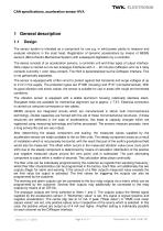
CAN specifications, acceleration sensor NVA The sensor system is intended as a component for use e.g. in wind power plants to measure and evaluate vibrations in the mast head. Registration of dynamic accelerations by means of MEMS sensors (Micro-Electro-Mechanical System) with subsequent digitisation by a controller. The device consists of an acceleration sensors, a controller unit and three types of output interface. Data output is carried out via two analogue interfaces with 4 ... 20 mA plus CANopen and via 4 relay contacts (currently 1 error relay contact). The NVA is parameterised via the...
Open the catalog to page 5
CAN specifications, acceleration sensor NVA Evaluation of the switching points of the alarm and warning level outputs takes place at the filter output. On evaluation of the switching points, conversion to the output value amount always takes place, irrespective of the filter's measurement type setting. The CANopen interface can be used to set the parameters and call up the 6 filters' outputs. With the exception of the filter characteristics, all parameters are programmable. For further information concerning the electrical and mechanical specification please refer to datasheet NVA12634, where...
Open the catalog to page 6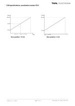
CAN specifications, acceleration sensor NVA
Open the catalog to page 7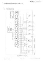
CAN specifications, acceleration sensor NVA Flow diagrams Figure 1: System in complete
Open the catalog to page 8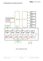
CAN specifications, acceleration sensor NVA Anwendungsparameter Filtereinstellungen Limiteinstellungen Relais Konfiguration Abgleichparameter Array T_FILTER_OUT Priorität: 4 Delay: 10 Stackgröße: 100 Priorität: 4 Delay: 10 Stackgröße: 100 Priorität: +2 Delay: Stackgröße: 100 Priorität: +1 Delay: Stackgröße: 100 Priorität: +1 Delay: Stackgröße: 100 Priorität: +0 Delay: Stackgröße: 100 Priorität: +0 Delay: Stackgröße: 100 Priorität: +0 Delay: Stackgröße: 100 CAN Priorität: 1 Delay: Stackgröße: 100 Datentyp: CANOPEN_TRANSMIT_MSG Länge: 8 PDO Datentyp: CANOPEN_MSG Länge: 4 NMT Datentyp: CANOPEN_MSG...
Open the catalog to page 9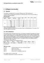
CAN specifications, acceleration sensor NVA 2 CANopen functionality 2.1 General The software is equipped with the standard CANopen stack (TWK development). The baud rates are implemented according to the following table. The baud rate of 20 kBit/s is defined as the default setting. Bit timing table EMC error codes: 0x FFFF 0x8120 0x8140 0x8110 Customer-specific error, error in the sensor system Passive error status Return from bus off status Overrun error; a message has been lost Error register codes, see object 1001. The data are implemented on the bus in Intel format. Datum: 21.11.2018 Page...
Open the catalog to page 10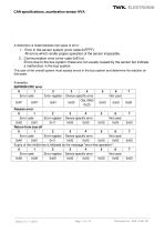
CAN specifications, acceleration sensor NVA A distinction is made between two types of error: 1. Error in the sensor system (error code OxFFFF) All errors which render proper operation of the sensor impossible. 2. Communication error (error code 0x81xx) Errors due to the bus system; these are not usually caused by the sensor but indicate a malfunction in the bus system. The user of the overall system must assess errors in the bus system and determine his reaction on this basis. Examples: EEPROM CRC error Datum: 21.11.2018 Page 11 of 51 Document no.: NVA 12657 GE
Open the catalog to page 11
CAN specifications, acceleration sensor NVA Table of all objects contained in the profile Datum: 21.11.2018 Page 12 of 51 Document no.: NVA 12657 GE
Open the catalog to page 12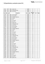
Datum: 21.11.2018 Page 13 of 51 Document no.: NVA 12657 GE
Open the catalog to page 13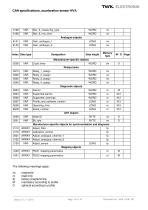
The following meanings apply: rw read/write M mandatory according to profile O optional according to profile Datum: 21.11.2018 Page 14 of 51 Document no.: NVA 12657 GE
Open the catalog to page 14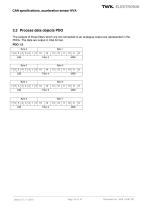
3.2 Process data objects PDO The outputs of those filters which are not connected to an analogue output are represented in the PDOs. The data are output in Intel format. PDO 1/2 Datum: 21.11.2018 Page 15 of 51 Document no.: NVA 12657 GE
Open the catalog to page 15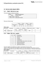
CAN specifications, acceleration sensor NVA Datum: 21.11.2018 Page 16 of 51 Document no.: NVA 12657 GE
Open the catalog to page 16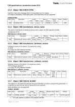
CAN specifications, acceleration sensor NVA 3.3.3 Object 1005 COB-ID-SYNC Identifier of the sync message which is transmitted from the master. No range or plausibility check takes place. 29-bit identifiers are not supported. The node address is added to the selec Datum: 21.11.2018 Page 17 of 51 Document no.: NVA 12657 GE
Open the catalog to page 17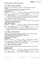
CAN specifications, acceleration sensor NVA 3.3.8 Object 1010 store_parameters On inputting "save” as the password in sub-index 01, all writable objects are saved to the E2PROM. The object cannot be changed on writing. Reading the object is possible. 1 (saving via command, page 93 DS 301 4.1) is returned. Store_parameters Datum: 21.11.2018 Page 18 of 51 Document no.: NVA 12657 GE
Open the catalog to page 18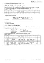
CAN specifications, acceleration sensor NVA 3.3.12 Object 1017 producer_heartbeat_time If a value greater than zero is entered here, the heartbeat message on the identifier guard COB ID + node ID is transmitted in the producer_heartbeat_time interval in ms. Producer_heartbeat_time 1) Written in factory programming status. Datum: 21.11.2018 Page 19 of 51 Document no.: NVA 12657 GE
Open the catalog to page 19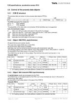
CAN specifications, acceleration sensor NVA The process data are output via two process data objects (PDOs). MSB LSB 1) On reading (upload), the node address is added to the selected identifier. Datum: 21.11.2018 Page 20 of 51 Document no.: NVA 12657 GE
Open the catalog to page 20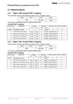
TWTC ELEKTRONIK CAN specifications, acceleration sensor NVA 3.5 Mapping objects 3.5.1 Object 1A00 transmit PDO 1 mapping The parameter contains the following coding for each "mapping” object: Datum: 21.11.2018 Page 21 of 51 Document no.: NVA 12657 GE
Open the catalog to page 21All TWK-ELEKTRONIK GmbH catalogs and technical brochures
 Rotary encoder TBN58/C3 manual
50 Pages
 Rotary encoder TBN58/C3
22 Pages
 Rotary encoder TBD Manual
26 Pages
 Rotary encoder TBD
12 Pages
 Rotary encoder TBE58
16 Pages
 Rotary encoder KRP - Manual
19 Pages
 Rotary encoder KRP
7 Pages
 Rotary encoder TBN58/S4 SIL2
22 Pages
 Rotary encoder TBN50/C3 manual
20 Pages
 Rotary encoder TBN50/C3
22 Pages
 Rotary encoder HBN/S3 SIL2
16 Pages
 Product range 2022
64 Pages
 Image brochure TWK
28 Pages
 Inclinometer NBA51
6 Pages
 Incremental encoder FOI
7 Pages
 Rotary encoder TBA42
16 Pages
 Rotary encoder TRA42
16 Pages
 Rotary encoder TRN58/S4 SIL2
22 Pages
 Rotary encoder TRN58/C3 manual
50 Pages
 Rotary encoder TRN58/C3
22 Pages
 Rotary encoder TRN42/S4 SIL2
22 Pages
 Manual TRN50/C3
86 Pages
 Rotary encoder TRN50/C3
22 Pages
 Rotary encoder TRN42/C3 manual
86 Pages
 Rotary encoder TRN42/C3
22 Pages
 Rotary encoder TBN42/S4 SIL2
22 Pages
 Rotary encoder TBN42/C3 manual
86 Pages
 Rotary encoder TBN42/C3
22 Pages
 Rotary encoder TRE58
16 Pages
 Rotary encoder TRT manual
40 Pages
 Rotary encoder TRT
14 Pages
 Switching cam encoder NOCE
14 Pages
 Switching cam encoder NOCA
17 Pages
 Vibration sensor NVT/S3 PLd
12 Pages
 Vibration sensor NVA
12 Pages
 Inclinometer NBN
17 Pages
 Incremental encoder TBI42
6 Pages
 Vibration sensor NVA/S3 PLd
15 Pages
 Rotary transducer PMR411
1 Page
 Rotary encoder TRT/S3 SIL2
13 Pages
 Rotary transducer VP12
1 Page
 Switching cam encoder NOCN
22 Pages
 Inclination sensor NBT manual
21 Pages
 Inclination sensor NBT
10 Pages
 Inclinometer NBA
17 Pages
 Inclinometer NBT/S3 SIL2/PLd
12 Pages
 Inclinometer NBN/S3 SIL2
13 Pages
 Rotary encoder TBE50
16 Pages
 Rotary encoder HBE
14 Pages
 Rotary encoder TRK manual
18 Pages
 Rotary encoder TRK
11 Pages
 Rotary encoder TMN50 manual
22 Pages
 Rotary encoder TMN50
6 Pages
 Rotary encoder TRK/S3 SIL2
14 Pages
 Rotary encoder TRE42
6 Pages
 Rotary encoder TRE50
6 Pages
 Rotary encoder TRA50
6 Pages
 Rotary encoder TBE42
6 Pages
 Rotary encoder TME42
6 Pages
 Rotary encoder TRD manual
26 Pages
 Rotary encoder TRD
12 Pages
 Rotary encoder TME50
6 Pages
 Rotary encoder TBN36
6 Pages
 Rotary encoder TMA50
6 Pages
 Rotary encoder TMN42 manual
22 Pages
 Rotary encoder TMN42
6 Pages
 Rotary encoder TMA42
6 Pages
 Rotary encoder TBA50
16 Pages
 Rotary encoder TBE36 manual
22 Pages
 Rotary encoder TBE36
6 Pages
 Rotary encoder TBN42
6 Pages
 Rotary encoder TBN37
8 Pages
 Rotary encoder TBA37
7 Pages
 Rotary encoder TBB50
16 Pages
 Rotary encoder PBA12
2 Pages
 Rotary encoder TBA36
6 Pages
 Rotary encoder TKA60
2 Pages
 Rotary encoder TKN46 manual
22 Pages
 Rotary encoder TKN46
7 Pages




- Angular encoder
- Incremental encoder
- Incremental rotary encoder
- Absolute rotary encoder
- Tilt sensor
- Industrial rotary encoder
- Magnetic rotary encoder
- Displacement transducer
- Linear displacement sensor
- Digital inclination sensor
- Aluminum rotary encoder
- Stainless steel rotary encoder
- Single-turn rotary encoder
- MEMS inclination sensor
- Flange rotary encoder
- Ultra-rugged rotary encoder
- Multi-axis tilt sensor
- SSI angular encoder
- Multi-turn rotary encoder
- Analog displacement transducer