- Catalogs
- TWK-ELEKTRONIK GmbH
- Vibration sensor NVA/S3 PLd
- Company
- Products
- Catalogs
- News & Trends
- Exhibitions
Vibration sensor NVA/S3 PLd
1 /15Pages

Vibration sensor NVA/S3 PLd
1 /15Pages
Catalog excerpts
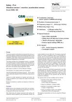
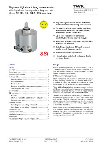
SUPREME SENSORING TWTC Document No.: NVA 13482 ME Date: 21.03.2019 CflNopGQ safety Certified EN ISO 13849: PLd ■ Contactless, wear-free sensor system in MEMS technology ■ Number of measurement axes: 2 ■ Frequency range: 0.1 ... 60 Hz (opt. 0.05 Hz) ■ Measuring range: ± 2 g ■ Interfaces: ♦ CANopen safety PLd ♦ 2 switching contacts PLd ■ Special features: ♦ Type of filter selectable ♦ 'Safety Shut off' SSO due to heavy strokes ♦ "Switch off phasing" adjustable ♦ Various signal settings (RMS etc.) ■ On request ♦ 'FFT' - fourier frequency detection ♦ 2 analogue outputs Design The sensor system is intended as a component for use e.g. in wind power plants to measure and evaluate vibrations in the mast head. Registration of dynamic accelerations by means of MEMS sensors (Micro-Electro-Mechanical System) with subsequent digitisation by a controller. The device consists of an acceleration sensor, a controller unit and three types of output interface. The main feature is two safety switching contacts (potential-free), which can be used e.g. in the safety chain to undertake safety shut-off in the event of excessively high acceleration values. Data output is carried out via the CANopen interface. The standard or the safety profile can be selected. There are additionally two analogue outputs 4 ... 20 mA, which can be optionally assigned to two of the three measurement axes. Thanks to its high resistance to vibration and shock, the sensor is suitable for use in areas with rough environmental conditions. Electrical connection is carried out using two or three connectors. Function MEMS sensors are integrated circuits which are manufactured in silicon bulk micromechanics technology. They have a long service life and are very robust. After determining the steady component and scaling, the measured values supplied by the acceleration sensor are made available to the six filter units. The steady component arises as a result of installation which is not precisely horizontal, with the result that part of the earth's gravitational field would also be measured. The offset which occurs in the measured vibration value curve (zero point shift) due to the steady component is determined by means of calculation (distribution of the positive and negative measured values around the zero point) and is subtracted. The pure alternating component is output within a matter of 20 seconds. This calculation takes place continually. This function can be shut off in the factory. The filter units can be individually programmed in the filter characteristics for frequency selection in the factory (low pass or band pass). They can be assigned to axes x, y or the resulting ones. Certain types of filter (kind, order, frequency limits) can be defined by the customer and can then be selected via CANopen. The signals which are then available can be used for: ♦ activation of the safety switching outputs, time delay on demand (g limit values and assignment) ♦ output on CANopen / CANopen safety ♦ selection of momentary or RMS output or peak or integral output ♦ output on analogue outputs (not certified) (amplification factor and assignment) The majority of parameters can be set using the CANopen interface. TWK-ELEKTRONIK GmbH BismarckstraBe 108 [email protected] visit us at | twk.de
Open the catalog to page 1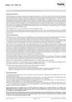
See document NVA13660 for detailed information General information The vibration sensor measures on two axes in a frequency spectrum from 0.1 to 60 Hz (Option: 0.05 to 60 Hz). This spectrum can be subdivided into a maximum of 6 frequency ranges. The frequency ranges are set in the factory. All acceleration values acting within the relevant frequency window are registered and are output firstly as an analogue value (4 ... 20 mA, max. two outputs possible) and secondly as a digital value via CANopen or CANopen safety. The acceleration values which are present are additionally compared with limit...
Open the catalog to page 2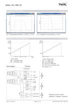
SUPREME SENSORING Examples for fiter output Amplitude vs f Diagram for analogue output I0(a) Output: signed ■ x, momentary value ■ y, momentary value Block Diagram x or y, RMS value x or y, Peak value S=V(x2+y2), RMS value S=V(x2+y2), momentary value Integral 1 or 2 Following version is shown: CANopen + Analogue + Switches Date: 21.03.2019 Page 3 of 15 Document No. NVA 13482 ME
Open the catalog to page 3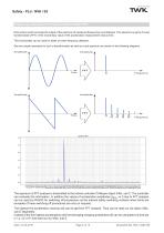
Frequency detection by Fourier transformation FFT NVA version which provides the output of the spectrum of measured frequencies via CANopen. This spectrum is get by Fourier transformation (FFT) of the momentary value of the acceleration measurement versus time. This functionality can be used for blade or tower frequency detection. See two simple examples for such a transformation as well as a real spectrum are shown in the following diagrams. Amplitude The spectrum of FFT analysis is transmitted to the turbine controller CANopen object 340x, sub C. The controller can evaluate this information....
Open the catalog to page 4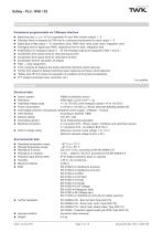
Safety - PLd - NVA / S3Programmable features Parameters programmable via CANopen interface ■ Measuring axis: x, y or V(x2+y2) separately for each filter (means output) 1 - 6 ■ Filtertype which is prepared by TWK due to customers requirements for each output 1 - 6 ■ Signal type at filter output 1 - 6: momentary value, RMS mean value, peak value, integration value ■ Averaging time for signal type 'RMS', degressive time for peak, integration time ■ Amplification for analogue outputs 4 ... 20 mA (Analoge outputs are assigned to filter 1 and 2) * ■ Acceleration limit values (limit) for relay warning...
Open the catalog to page 5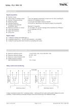
Signal acquisition ■ Number of axes: ■ Value output on analogue output: ■ Number of frequency bands: ■ Measuring range: ■ Sampling frequency: ■ Accuracy of the measured acceleration value: ■ Maximum inclination vs. horizon: ■ Lower limit frequency: ■ Upper limit frequency: ■ Set-up time: 2 x and y as separate components or vector sum of x and y (resulting R) maximum of 6 (Setting ex works) ± 2 g for each axis (higher values on request) 120 to 800 Hz, depending on the frequency range of according filter Standard 5 % (typically) 15° (at angles >15° an error message will be transferred by CANopen)...
Open the catalog to page 6All TWK-ELEKTRONIK GmbH catalogs and technical brochures
 Rotary encoder TBN58/C3 manual
50 Pages
 Rotary encoder TBN58/C3
22 Pages
 Rotary encoder TBD Manual
26 Pages
 Rotary encoder TBD
12 Pages
 Rotary encoder TBE58
16 Pages
 Rotary encoder KRP - Manual
19 Pages
 Rotary encoder KRP
7 Pages
 Rotary encoder TBN58/S4 SIL2
22 Pages
 Rotary encoder TBN50/C3 manual
20 Pages
 Rotary encoder TBN50/C3
22 Pages
 Rotary encoder HBN/S3 SIL2
16 Pages
 Product range 2022
64 Pages
 Image brochure TWK
28 Pages
 Inclinometer NBA51
6 Pages
 Incremental encoder FOI
7 Pages
 Rotary encoder TBA42
16 Pages
 Rotary encoder TRA42
16 Pages
 Rotary encoder TRN58/S4 SIL2
22 Pages
 Rotary encoder TRN58/C3 manual
50 Pages
 Rotary encoder TRN58/C3
22 Pages
 Rotary encoder TRN42/S4 SIL2
22 Pages
 Manual TRN50/C3
86 Pages
 Rotary encoder TRN50/C3
22 Pages
 Rotary encoder TRN42/C3 manual
86 Pages
 Rotary encoder TRN42/C3
22 Pages
 Rotary encoder TBN42/S4 SIL2
22 Pages
 Rotary encoder TBN42/C3 manual
86 Pages
 Rotary encoder TBN42/C3
22 Pages
 Rotary encoder TRE58
16 Pages
 Rotary encoder TRT manual
40 Pages
 Rotary encoder TRT
14 Pages
 Switching cam encoder NOCE
14 Pages
 Switching cam encoder NOCA
17 Pages
 Vibration sensor NVT/S3 PLd
12 Pages
 Vibration sensor NVA
12 Pages
 Inclinometer NBN
17 Pages
 Incremental encoder TBI42
6 Pages
 Rotary transducer PMR411
1 Page
 Rotary encoder TRT/S3 SIL2
13 Pages
 Rotary transducer VP12
1 Page
 Switching cam encoder NOCN
22 Pages
 Inclination sensor NBT manual
21 Pages
 Inclination sensor NBT
10 Pages
 Inclinometer NBA
17 Pages
 Inclinometer NBT/S3 SIL2/PLd
12 Pages
 Inclinometer NBN/S3 SIL2
13 Pages
 Rotary encoder TBE50
16 Pages
 Rotary encoder HBE
14 Pages
 Rotary encoder TRK manual
18 Pages
 Rotary encoder TRK
11 Pages
 Rotary encoder TMN50 manual
22 Pages
 Rotary encoder TMN50
6 Pages
 Rotary encoder TRK/S3 SIL2
14 Pages
 Rotary encoder TRE42
6 Pages
 Rotary encoder TRE50
6 Pages
 Rotary encoder TRA50
6 Pages
 Rotary encoder TBE42
6 Pages
 Rotary encoder TME42
6 Pages
 Rotary encoder TRD manual
26 Pages
 Rotary encoder TRD
12 Pages
 Rotary encoder TME50
6 Pages
 Rotary encoder TBN36
6 Pages
 Rotary encoder TMA50
6 Pages
 Rotary encoder TMN42 manual
22 Pages
 Rotary encoder TMN42
6 Pages
 Rotary encoder TMA42
6 Pages
 Rotary encoder TBA50
16 Pages
 Rotary encoder TBE36 manual
22 Pages
 Rotary encoder TBE36
6 Pages
 Rotary encoder TBN42
6 Pages
 Rotary encoder TBN37
8 Pages
 Rotary encoder TBA37
7 Pages
 Rotary encoder TBB50
16 Pages
 Rotary encoder PBA12
2 Pages
 Rotary encoder TBA36
6 Pages
 Rotary encoder TKA60
2 Pages
 Rotary encoder TKN46 manual
22 Pages
 Rotary encoder TKN46
7 Pages


- Angular encoder
- Incremental encoder
- Incremental rotary encoder
- Absolute rotary encoder
- Tilt sensor
- Magnetic rotary encoder
- Industrial rotary encoder
- Displacement transducer
- Linear displacement sensor
- Digital inclination sensor
- Aluminum rotary encoder
- Stainless steel rotary encoder
- Single-turn rotary encoder
- MEMS inclination sensor
- Flange rotary encoder
- Multi-axis tilt sensor
- Ultra-rugged rotary encoder
- SSI angular encoder
- Multi-turn rotary encoder
- Analog displacement transducer