- Catalogs
- TWK-ELEKTRONIK GmbH
- Switching cam encoder NOCE
- Company
- Products
- Catalogs
- News & Trends
- Exhibitions
Switching cam encoder NOCE
1 /14Pages

Switching cam encoder NOCE
1 /14Pages
Catalog excerpts
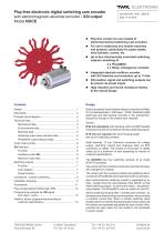
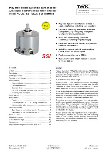
Play-free electronic digital switching cam encoder with electromagnetic absolute encoder / SSI output Model NOCE Play-free version for use instead of electromechanical switching cam encoders For use in stationary and mobile machines and systems, particularly for power plants, wind turbines, cranes, etc. Up to four electronically controlled switching outputs consisting of - 2 x PhotoMOS - 2 x Relay: Changeover contacts Integrated absolute multiturn encoder with SSI interface and resolution up to 13 bits SSI position signal and switching outputs can be preset via preset inputs High vibration and shock resistance thanks to the robust design Robust housing in dual-chamber design in aluminium (AlMgSi1) or stainless steel (1.4305 resp. 1.4404). Shaft with radial shaft seal and ball bearing mounted in the prechamber. Electronics housed in the sealed main chamber. TWK-ELEKTRONIK GmbH Heinrichstrasse 85 Version: Ø 64 mm (standard) with clamping collar and M6 threaded holes plus two device connectors and two switching outputs. Ø 79 mm (on request) with short housing length and up to 6 switching contacts Shaft diameter 12 mm. Electrical connection for voltage supply, switching outputs and analogue data via M12 connectors or cables. The number of connectors or cables varies (up to a maximum of two) depending on version or customer specifications. The NOCE64 has four switching contacts (6 at model NOCE79 possible). The version with two contacts contains two mechanical relays with changeover contacts. The version with four contacts contains two additional semiconductors (PhotoMOS) which represent a NO contact each. Each semiconductor switching contact is separated by an Opto - Isolator from the rest potential of the NOCE, so that these switching outputs - as well as the relays – are galvanically isolated. The PhotoMOS units can switch AC and DC. All four switching contacts (NO - normally open contacts - by the relays) are closed during normal operation, thus providing a constant current flow. When a contact switching value (shaft position) is reached the appropriate contact opens. All limit values are separately adjustable for each contact. Also, contacts are open when the cam switch is not connected to power supply.
Open the catalog to page 1
Electronic digital switching cam encoder model NOCE Description General functional principle long service lives resp. wear-free PhotoMOS semicondutors which are as well galvanically separated. This involves a play-free electronic switching cam encoder (abbreviated to: NOCE) with a maximum of four galvanically separated switching outputs, which can be set by the customer and which are activated or deactivated depending on the relevant position of the drive shaft. A parameterisable multiturn absolute encoder with SSI interface plus the switching cam encoder printed circuit board with separate controller...
Open the catalog to page 2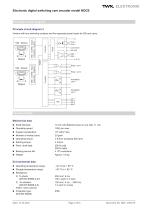
Electronic digital switching cam encoder model NOCE Principle circuit diagram Principle circuit diagram 2 Version with four switching contacts and five separate preset inputs for SSI and cams. data + data - VS (0 V) Relay / cam 1 Relay / cam 2 Hall - Sensor code sense set input SINE - COSINE - Signal Interpolator - Singelturn Hall - Sensor SINE - COSINE - Signal Interpolator - Multiturn Technical Data Mechanical data Shaft diameter: 12 mm with flattened area on one side, 11 mm Moment of inertia (rotor): Perm. shaft load: Bearing service life: 250 N axial 250 N radial ≥ 109 revolutions...
Open the catalog to page 3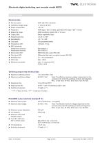
Electrical data ■ Sensor system: ■ Operating voltage range: ■ Power consumption: ■ Resolution: ■ Measuring range: ■ Output code: ■ Absolute accuracy: ■ Repeatability: ■ Code path: ■ Temperature drift: ■ EMC standards: Interference emission: Interference immunity: ■ Serial output SSI: ■ Clock input SSI: ■ Monoflop time: ■ Clock rate: ■ Electrical connection: ASIC with HALL elements 11 VDC to 28 VDC < 2.5 W 4096 steps / 360° (12-bits), optionally 8192 steps / 360° (13 bits) 4096 revolutions (option 256 or 16 revs.) Binary (optionally Gray) ± 0.25 % / 360° ± 0.1 % / 360° CW (parameterisable) ± 20...
Open the catalog to page 4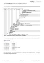
Standard version Electrical and mechanical variants 01 Standard Absolute encoder interface: E SS/ Electrical connections: S Device connector M12 K Cable connection Measuring range: 16 256 Revolutions 4096 Code: R Binary / G Gray Resolution: 4096 Steps / 360°, 8192 steps / 360° at maximum Number of switching outputs: 2 2 Switching outputs, 4 at maximum (6 at model NOCE79) Housing material: A Aluminium S Stainless steel 1.4305 V Stainless steel 1.4404 Flange: K Clamped flange Design form: 64 0 64 mm (Other flange designs on request, i.e. 0 58 mm or 79 mm) NOCE Electronic digital switching cam encoder...
Open the catalog to page 5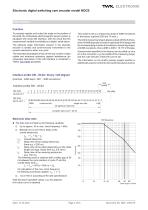
Function To precisely register and output the angle or the position of the shaft, the contactless electromagnetic sensor system is equipped with serial SSI interface, with the result that the measurement variable is available as a digital, serial datum. The absolute angle information present in the absolute encoder is serially and synchronously transmitted to the receiver electronics within one cycle. The essential advantages of this are the low number of data cables and extensive protection against interference (an exhaustive description of the SS/ interface is contained in TWK's SS/ 10630 pamphlet)....
Open the catalog to page 6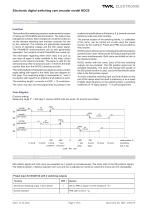
Function The function ofthe switching outputs is implemented by means of relays and PhotoMOS semiconductors. The relays have changeover contacts. Each changeover contact is routed out via the relevant switching cam encoder connector for use by the customer. The contacts are galvanically separated in terms of operating voltage and the SSI output signal. The PhotoMOS semiconductors are as well galvanically separated. Two contacts of each PhotoMOS are routed out. The information regarding when which relay is to pick up and drop off again is made available to the relay control system by the internal...
Open the catalog to page 7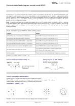
On activation of the preset function for the switching outputs in accordance with the table, the relevant switching flank (see cam diagram) is set precisely at the current shaft position. It can be ascertained that the switching output switches at this point by rotating the shaft around this position. On use of the programmer PMA-NOC-03, this can be recognised by the fact that the LED comes on and goes off. The switching contact (or LED) does not necessarily react immediately to the preset process without a shaft position change. Note: The switching flanks of the individual cams always refer...
Open the catalog to page 8All TWK-ELEKTRONIK GmbH catalogs and technical brochures
 Rotary encoder TBN58/C3 manual
50 Pages
 Rotary encoder TBN58/C3
22 Pages
 Rotary encoder TBD Manual
26 Pages
 Rotary encoder TBD
12 Pages
 Rotary encoder TBE58
16 Pages
 Rotary encoder KRP - Manual
19 Pages
 Rotary encoder KRP
7 Pages
 Rotary encoder TBN58/S4 SIL2
22 Pages
 Rotary encoder TBN50/C3 manual
20 Pages
 Rotary encoder TBN50/C3
22 Pages
 Rotary encoder HBN/S3 SIL2
16 Pages
 Product range 2022
64 Pages
 Image brochure TWK
28 Pages
 Inclinometer NBA51
6 Pages
 Incremental encoder FOI
7 Pages
 Rotary encoder TBA42
16 Pages
 Rotary encoder TRA42
16 Pages
 Rotary encoder TRN58/S4 SIL2
22 Pages
 Rotary encoder TRN58/C3 manual
50 Pages
 Rotary encoder TRN58/C3
22 Pages
 Rotary encoder TRN42/S4 SIL2
22 Pages
 Manual TRN50/C3
86 Pages
 Rotary encoder TRN50/C3
22 Pages
 Rotary encoder TRN42/C3 manual
86 Pages
 Rotary encoder TRN42/C3
22 Pages
 Rotary encoder TBN42/S4 SIL2
22 Pages
 Rotary encoder TBN42/C3 manual
86 Pages
 Rotary encoder TBN42/C3
22 Pages
 Rotary encoder TRE58
16 Pages
 Rotary encoder TRT manual
40 Pages
 Rotary encoder TRT
14 Pages
 Switching cam encoder NOCA
17 Pages
 Vibration sensor NVT/S3 PLd
12 Pages
 Vibration sensor NVA
12 Pages
 Inclinometer NBN
17 Pages
 Incremental encoder TBI42
6 Pages
 Vibration sensor NVA/S3 PLd
15 Pages
 Rotary transducer PMR411
1 Page
 Rotary encoder TRT/S3 SIL2
13 Pages
 Rotary transducer VP12
1 Page
 Switching cam encoder NOCN
22 Pages
 Inclination sensor NBT manual
21 Pages
 Inclination sensor NBT
10 Pages
 Inclinometer NBA
17 Pages
 Inclinometer NBT/S3 SIL2/PLd
12 Pages
 Inclinometer NBN/S3 SIL2
13 Pages
 Rotary encoder TBE50
16 Pages
 Rotary encoder HBE
14 Pages
 Rotary encoder TRK manual
18 Pages
 Rotary encoder TRK
11 Pages
 Rotary encoder TMN50 manual
22 Pages
 Rotary encoder TMN50
6 Pages
 Rotary encoder TRK/S3 SIL2
14 Pages
 Rotary encoder TRE42
6 Pages
 Rotary encoder TRE50
6 Pages
 Rotary encoder TRA50
6 Pages
 Rotary encoder TBE42
6 Pages
 Rotary encoder TME42
6 Pages
 Rotary encoder TRD manual
26 Pages
 Rotary encoder TRD
12 Pages
 Rotary encoder TME50
6 Pages
 Rotary encoder TBN36
6 Pages
 Rotary encoder TMA50
6 Pages
 Rotary encoder TMN42 manual
22 Pages
 Rotary encoder TMN42
6 Pages
 Rotary encoder TMA42
6 Pages
 Rotary encoder TBA50
16 Pages
 Rotary encoder TBE36 manual
22 Pages
 Rotary encoder TBE36
6 Pages
 Rotary encoder TBN42
6 Pages
 Rotary encoder TBN37
8 Pages
 Rotary encoder TBA37
7 Pages
 Rotary encoder TBB50
16 Pages
 Rotary encoder PBA12
2 Pages
 Rotary encoder TBA36
6 Pages
 Rotary encoder TKA60
2 Pages
 Rotary encoder TKN46 manual
22 Pages
 Rotary encoder TKN46
7 Pages


- SARRALLE rotary encoder
- SARRALLE incremental encoder
- SARRALLE incremental rotary encoder
- SARRALLE absolute rotary encoder
- SARRALLE inclinometer
- SARRALLE magnetic rotary encoder
- Industrial rotary encoder
- Displacement transducer
- Linear displacement sensor
- SARRALLE digital inclinometer
- SARRALLE aluminum rotary encoder
- SARRALLE stainless steel rotary encoder
- SARRALLE single-turn rotary encoder
- MEMS inclination sensor
- Flange rotary encoder
- Multi-axis tilt sensor
- SARRALLE ultra-rugged rotary encoder
- SSI angular encoder
- SARRALLE multi-turn rotary encoder
- Analog displacement transducer