
- Catalogs
- TWK-ELEKTRONIK GmbH
- Switching cam encoder NOCE /S3- SIL2/ SSI Interface

Switching cam encoder NOCE /S3- SIL2/ SSI Interface
Switching cam encoder NOCE /S3- SIL2/ SSI Interface
Catalog excerpts
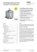
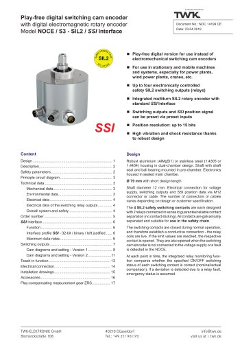
Play-free digital switching cam encoder with digital electromagnetic rotary encoder Model NOCE / S3 - SIL2 / SSI Interface lay-free digital version for use instead of P electromechanical switching cam encoders or use in stationary and mobile machines F and systems, especially for power plants, wind power plants, cranes, etc. p to four electronically controlled U safety SIL2 switching outputs (relays) ntegrated multiturn SIL2 rotary encoder with I witching outputs and SSI position signal S can be preset via preset inputs Position resolution: up to 15 bits igh vibration and shock resistance thanks H Robust aluminium (AlMgSi1) or stainless steel (1.4305 or 1.4404) housing in dual-chamber design. Shaft with shaft seal and ball bearing mounted in pre-chamber. Electronics housed in sealed main chamber. Ø 79 mm with short design length Shaft diameter 12 mm. Electrical connection for voltage supply, switching outputs and SSI position data via M12 connector or cable. The number of connectors or cables varies depending on design or customer specification. The 4 SIL2 safety switching contacts are each designed with 2 relays connected in series to guarantee reliable contact separation (no contact sticking). All contacts are galvanically separated and suitable for use in the safety chain. The switching contacts are closed during normal operation, and therefore establish a conductive connection - the relay coils are live. If the limit values are reached, the respective contact is opened. They are also opened when the switching cam encoder is not connected to the voltage supply or a fault is detected in the NOCE. At each point in time, the integrated relay monitoring function compares whether the specified ON/OFF switching status of each switching contact is correct (nominal/actual comparison). If a deviation is detected due to a relay fault, emergency status is assumed. TWK-ELEKTRONIK GmbH Bismarckstraße 108 [email protected] visit
Open the catalog to page 1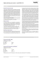
Digital switching cam encoder - model NOCE / S3Description General functional principle This involves a play-free electronic switching cam encoder (abbreviated to: NOCE) with a maximum of four galvanically separated SIL2 switching outputs that can be set by the customer, and which are activated or deactivated depending on the respective position of the drive shaft. A parameteris-able multiturn absolute encoder with SSI interface and the switching cam encoder PCB with separate controller are integrated in the compact housing. The SS/ interface can be preset, the encoding direction is adjustable...
Open the catalog to page 2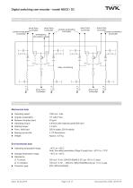
SUPREME SENSORING Principle circuit diagram 2 contacts shown. A total of 4 available drive from drive from Controller Controller drive from drive from Controller Controller Technical data Mechanical data ■ Operating speed: ■ Angular acceleration: ■ Moment of inertia (rotor): ■ Operating torque: ■ Starting torque: ■ Perm. shaft load: ■ Bearing service life: ■ Weight: Environmental data ■ Operating temperature range: ■ Storage temperature range: ■ Resistance: □ To shock: □ To vibration: ■ Protection type: 1000 rpm max. 105 rad/s2 max. 20 gcm2 s 8 Ncm (with rotational speed 500 rpm ) < 4 Ncm 250...
Open the catalog to page 3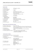
SUPREME SENSORING Technical data Electrical data ■ Sensor system: ■ Operating voltage range: ■ Power consumption: ■ Switch-on current: ■ Resolution: ■ Measuring range: ■ Output code: ■ Absolute accuracy: ■ Repeatability: ■ Code path: ■ EMC standards: Interference emission: Interference immunity: ■ Output serial SS/: ■ Clock input SS/: ■ Monoflop time: ■ Clock rate: ■ Electrical connection: GMR elements - redundant 9 ... 36 VDC < 3 W < 500 mA Up to 32,768 steps / 360° (15 bits) 4096 revolutions (optionally 256 or 16 revs.) Binary (optionally Gray) ± 0.25% / 360° (optionally ± 0.1% / 360°) ± 0.1%...
Open the catalog to page 4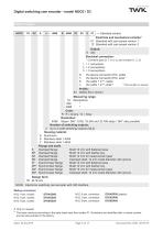
Digital switching cam encoder - model NOCE / S3 Order number ^ Standard version Electrical and mechanical variants1 01 Standard with cam preset version 1 12 Standard with cam preset version 2 Output: E SS/ Electrical connection: ^Combine type (S, T, K or L) and number (1, 2, 3) = 1 connection = 2 connections = 3 connections Via device connector M12, radial Via device connector M12, axial 1 Via cable 1 m2, radial "other lengths on request Profile: S3 Safety SIL2 version Measuring range: 16 Revolutions 256 '' Code: R R = binary / G = Gray Resolution: 4096 Steps / 360°. 8192, 16,384 and 32,768 steps...
Open the catalog to page 5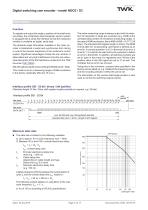
Digital switching cam encoder - model NOCE / S3 SSI Interface Function To register and output the angle or position of the shaft more accurately, the contactless electromagnetic sensor system is equipped with a serial SSI interface so that the measured variable is available as digital, serial data. The absolute angle information available in the rotary encoder is transferred in serial and synchronous form during a cycle to the receiver electronics in the customer's control system. Significant advantages include the low number of data cables and very high interference immunity (an exhaustive description...
Open the catalog to page 6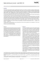
Digital switching cam encoder - model NOCE / S3 Switching outputs Function The function of the switching outputs is implemented using relays. Two relays are connected in series per switching output. This measure significantly increases reliable separation of the contacts, even if one relay does not separate (contact sticking). In terms of operating voltage and the SSI output signal, the contacts are galvanically separated. The relay monitoring function detects whether a relay contact is open or closed as specified by the controller - i.e. whether it has the required switching status (ACTUAL status...
Open the catalog to page 7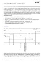
Digital switching cam encoder - model NOCE / S3 Cam diagrams and setting - Version 1 To define the position of the switching flanks, the relative position of all cams to Cam1 must be specified for each switching flank (cam) on ordering (a, b and c → e.g. in shaft revolutions). With Cam Preset, all switching flanks are shifted en bloc without changing their position relative to one another. The desired position in the switching flank ensemble (usage of d) or the desired switching flank as specified is located at the current shaft position. Example of the specification that the descending flank...
Open the catalog to page 8All TWK-ELEKTRONIK GmbH catalogs and technical brochures
 Rotary encoder TBN58/C3 manual
50 Pages
 Rotary encoder TBN58/C3
22 Pages
 Rotary encoder TBD Manual
26 Pages
 Rotary encoder TBD
12 Pages
 Rotary encoder TBE58
16 Pages
 Rotary encoder KRP - Manual
19 Pages
 Rotary encoder KRP
7 Pages
 Rotary encoder TBN58/S4 SIL2
22 Pages
 Rotary encoder TBN50/C3 manual
20 Pages
 Rotary encoder TBN50/C3
22 Pages
 Rotary encoder HBN/S3 SIL2
16 Pages
 Product range 2022
64 Pages
 Image brochure TWK
28 Pages
 Inclinometer NBA51
6 Pages
 Incremental encoder FOI
7 Pages
 Rotary encoder TBA42
16 Pages
 Rotary encoder TRA42
16 Pages
 Rotary encoder TRN58/S4 SIL2
22 Pages
 Rotary encoder TRN58/C3 manual
50 Pages
 Rotary encoder TRN58/C3
22 Pages
 Rotary encoder TRN42/S4 SIL2
22 Pages
 Manual TRN50/C3
86 Pages
 Rotary encoder TRN50/C3
22 Pages
 Rotary encoder TRN42/C3 manual
86 Pages
 Rotary encoder TRN42/C3
22 Pages
 Rotary encoder TBN42/S4 SIL2
22 Pages
 Rotary encoder TBN42/C3 manual
86 Pages
 Rotary encoder TBN42/C3
22 Pages
 Rotary encoder TRE58
16 Pages
 Rotary encoder TRT manual
40 Pages
 Rotary encoder TRT
14 Pages
 Switching cam encoder NOCE
14 Pages
 Switching cam encoder NOCA
17 Pages
 Vibration sensor NVT/S3 PLd
12 Pages
 Vibration sensor NVA
12 Pages
 Inclinometer NBN
17 Pages
 Incremental encoder TBI42
6 Pages
 Vibration sensor NVA/S3 PLd
15 Pages
 Rotary transducer PMR411
1 Page
 Rotary encoder TRT/S3 SIL2
13 Pages
 Rotary transducer VP12
1 Page
 Switching cam encoder NOCN
22 Pages
 Inclination sensor NBT manual
21 Pages
 Inclination sensor NBT
10 Pages
 Inclinometer NBA
17 Pages
 Inclinometer NBT/S3 SIL2/PLd
12 Pages
 Inclinometer NBN/S3 SIL2
13 Pages
 Rotary encoder TBE50
16 Pages
 Rotary encoder HBE
14 Pages
 Rotary encoder TRK manual
18 Pages
 Rotary encoder TRK
11 Pages
 Rotary encoder TMN50 manual
22 Pages
 Rotary encoder TMN50
6 Pages
 Rotary encoder TRK/S3 SIL2
14 Pages
 Rotary encoder TRE42
6 Pages
 Rotary encoder TRE50
6 Pages
 Rotary encoder TRA50
6 Pages
 Rotary encoder TBE42
6 Pages
 Rotary encoder TME42
6 Pages
 Rotary encoder TRD manual
26 Pages
 Rotary encoder TRD
12 Pages
 Rotary encoder TME50
6 Pages
 Rotary encoder TBN36
6 Pages
 Rotary encoder TMA50
6 Pages
 Rotary encoder TMN42 manual
22 Pages
 Rotary encoder TMN42
6 Pages
 Rotary encoder TMA42
6 Pages
 Rotary encoder TBA50
16 Pages
 Rotary encoder TBE36 manual
22 Pages
 Rotary encoder TBE36
6 Pages
 Rotary encoder TBN42
6 Pages
 Rotary encoder TBN37
8 Pages
 Rotary encoder TBA37
7 Pages
 Rotary encoder TBB50
16 Pages
 Rotary encoder PBA12
2 Pages
 Rotary encoder TBA36
6 Pages
 Rotary encoder TKA60
2 Pages
 Rotary encoder TKN46 manual
22 Pages
 Rotary encoder TKN46
7 Pages


- Incremental encoder
- Incremental rotary encoder
- Absolute rotary encoder
- Tilt sensor
- Industrial rotary encoder
- Magnetic rotary encoder
- Displacement transducer
- Linear displacement sensor
- Digital inclination sensor
- Aluminum rotary encoder
- Stainless steel rotary encoder
- Single-turn rotary encoder
- MEMS inclination sensor
- Flange rotary encoder
- Ultra-rugged rotary encoder
- Multi-axis tilt sensor
- SSI angular encoder
- Multi-turn rotary encoder
- Analog displacement transducer