
- Catalogs
- TWK-ELEKTRONIK GmbH
- Rotary encoder TRK/S3 SIL2 manual

Rotary encoder TRK/S3 SIL2 manual

Rotary encoder TRK/S3 SIL2 manual
- Scope: Applicable to TRKxx-xxxxxxxx4096S3xTxx encoders with PROFINET interface.
- Documentation: Includes system-specific instructions, manual, data sheet TRK 13348, connection assignment, and assembly instructions TZY10206.
- Proper Use: Designed for registering angular or linear positions and providing electrical output signals.
- Commissioning: Must be performed by a specialist electrician, ensuring protection against mechanical damage and adherence to specified limit values.
The TRK/S3 is an absolute electromagnetic rotary encoder with Failsafe over EtherCAT (FSoE) interface, suitable for safety-related applications up to SIL2 or PLd. It provides safe position and speed signals and supports CANopen over EtherCAT for parameter and diagnostic data handling.
- General: Uses 100BASE-TX Ethernet standard; requires CAT5 cables with a maximum length of 100m between subscribers.
- Electrical Connection: Separate connectors for power supply and EtherCAT system; recommended use of pre-assembled data cables with M12 connectors.
- Addressing: Subscriber address is automatically assigned by the EtherCAT master.
- Status LEDs: Indicate operational status and errors through specific flashing codes.
- XML File: Available for download to integrate the encoder into project planning tools like TwinCAT System Manager.
- Input Data: Includes command, position, speed, and status information.
- Output Data: Includes command, preset values, and control information.
Details on object directory, communication parameters, manufacturer-specific parameters, standardized device parameters, and FSoE communication parameters are provided for programming and diagnosis using CANopen over EtherCAT.
Provides a summary of diagnostic capabilities and error handling procedures.
- Installation: Instructions for installing the XML file and reading the EtherCAT bus structure.
- Project Creation: Steps for creating a TwinSAFE project and configuring FSoE settings.
Details the components included with the encoder delivery.
The velocity is determined by cyclically reading position data, measured in steps per gating time, adjustable between 10-1000 ms, with a default of 10 ms. The velocity is output as a 16-bit signed integer in Motorola format, with positive values indicating increasing position and negative for decreasing. The refresh rate is 1 ms, independent of gating time, with a resolution of 4096 steps per revolution.
The speed in rpm can be calculated using the formula: u = (v x 60000) / (t x 4096), where v is the encoder output and t is the gating time in ms.
The status word provides error and status information, with specific bits indicating errors such as save error, preset error, speed measuring range exceeded, and position error. An error is indicated by 0x81 in the error register and a flashing red status LED.
The preset value data format allows setting a reference value for position comparison, which must be within the range of 0 to (total number of steps - 1). The preset function is only executable when the encoder shaft is stationary.
The control word is a 16-bit format where bit 0 is used to activate the preset value.
The object directory contains parameters and diagnostic information, accessible via SDO messages, and is divided into communication parameters, manufacturer-specific parameters, standardized device parameters, and FSoE communication parameters.
These include device type, error register, device name, hardware and software versions, and parameters for storing and restoring default settings.
Includes settings for the encoder FSoE address and serial number, which are only modifiable in pre-operational status.
Parameters such as safety position and speed configuration can be set by the user and stored in the encoder's EEPROM. Changes require recalculating and storing a checksum.
These parameters follow the Modular Device Profile for Safety Modules Specification and include FSoE slave frame elements.
- FSoE Input Data (Object E601h): Contains sub-indices for safe position and speed values, error indicators, and speed limit checks. Refer to chapter 4.2 for detailed input data.
- FSoE Master Frame Elements (Object E700h): Includes master command, connection ID, and CRC values.
- FSoE Output Data (Object E701h): Contains preset values and control indicators. Detailed output data is in chapter 4.3.
- FSoE Slave Module Information (Object E900h): Provides connection ID, device type, vendor ID, product code, revision, and serial number.
- FSoE Connection Communication Parameter (Object E901h): Details version, safety address, connection ID, watchdog time, and device ID.
- FSoE Connection Diagnosis (Object EA00h): Describes connection states and diagnosis bits for errors like null message, watchdog expiration, and CRC errors.
- Error Causes and Remedies: Includes position errors, speed measuring range exceeded, preset errors, save errors, and internal errors like stack, CRC, RAM/XRAM, and program sequence errors. FSoE errors include watchdog and CRC errors.
- Installation and Configuration: Instructions for installing XML files, reading EtherCAT bus structure, and assigning FSoE addresses.
- Creating a TwinSAFE Project: Steps to create a safety project, configure the FSoE master system, and connect devices.
- FSoE Encoder Settings: Details on setting watchdog time and connecting ErrAcknowledge and RUN variables.
- Safety Program: Accessing rotary encoder data, configuring input types, and activating TwinCAT configuration.
- Includes an absolute encoder with EtherCAT FSoE interface, connection assignment, datasheet, user manual, certificates, and ESI file available for download.
Catalog excerpts

Absolute multiturn encoder TRK/S3 with Safety over EtherCAT® interface Relevant data sheet TRK 13348 User manual Translation of the original instructions TWK-ELEKTRONIK GmbH Heinrichstrasse 85 [email protected] www.twk.de
Open the catalog to page 1
COPYRIGHT: The Operating Instructions TRK13349 is owned by TWK-ELEKTRONIK GMBH and is protected by copyright laws and international treaty provisions. © 2017 by TWK-ELEKTRONIK GMBH POB 10 50 63 ■ 40041 Dusseldorf ■ Germany Tel. +49/211/96117-0 ■ Fax +49/211/63 77 05 [email protected] ■ www.twk.de Safety over EtherCAT® is registered trademark and patented technology, licensed by Beckhoff Automation GmbH, Germany Date: 20.11.2018 Page 2 of 30 Document no. TRK 13349 FE
Open the catalog to page 2
1. Safety instructions 1.1 Scope This user manual is valid exclusively for the following absolute encoders with PROFINET interface: 1.2 Documentation The following documents must be observed: • The owner's system-specific operating instructions • This user manual • Data sheet number TRK 13348 • The connection assignment enclosed with the device • Assembly instructions TZY10206 enclosed with the device 1.3 Proper use The TWK-ELEKTRONIK GmbH absolute encoders and linear transducers are used to register angular or linear positions and make their measured value available in the form of an electrical...
Open the catalog to page 5
2. General The TRK/S3 model is an absolute electromagnetic rotary encoder with Failsafe over EtherCAT (FSoE) interface. Thanks to additional internal monitoring measures, it is suitable for use in safety-related applications up to SIL2 or PLd. In addition to a safe position signal, the TRK/S3 also supplies a safe vehicle speed signal. Use of the CANopen over EtherCAT message (CoE) enables parameter and diagnostic data handling as familiar from CANopen. The EtherCAT interface according to IEC 61158-2 to 6 and the encoder profile CiA DSP406 plus the FSoE protocol as per Safety over EtherCAT Specification...
Open the catalog to page 6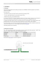
3. Installation 3.1 General The physical characteristics of the interface are based on the 100BASE-TX Ethernet standard in accordance with ISO/ I EC 8802-3. As a result of this: - The EtherCAT cable must at least meet the requirements according to CAT5. - The max. cable length between two subscribers may be 100 m. - Setting the baud rate is not possible/necessary. In the case of EtherCAT, the network topology normally has a linear structure. However, tree structures or branch-off lines may also be implemented by means of bus modules with an integrated switch port. In contrast to the EDP networks...
Open the catalog to page 7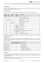
3.3 Addressing Manually setting the subscriber address is not necessary. It is assigned automatically by the EtherCAT master in accordance with the physical sequence in the bus. 3.4 Status LEDs Four LEDs are housed in the absolute encoder‘s connecting cap. These have the following meanings: 3.5 XML file An XML file (ESI file) to integrate the absolute encoder into a project planning tool is available for download on our website www.twk.de (under documentation). This describes the features of the EtherCAT subscriber in the standardised XML format. After integrating the XML file into the project...
Open the catalog to page 8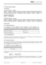
4.1 Overview Input data: Controler ^ Encoder The speed value is output as a 16-bit signed integer value in Motorola format (Big Endian). The following applies to the prefix: positive for increasing position negative for decreasing position The refresh rate of the velocity signal is independent from the selected gating time always 1 ms.. The speed measurement resolution is independent of the resolution of the encoder. It is always based on a resolution of 4096 steps per revolution. Date: 20.11.2018 Page 9 of 30 Document no. TRK 13349 FE
Open the catalog to page 9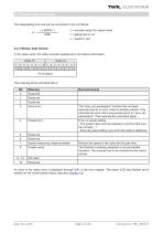
The steps/gating time unit can be converted to rpm as follows: v = encoder output for speed value t = gating time in ms u = speed in rpm 4.2.3 Status data format In the status word, the rotary encoder supplies error and status information. An entry in the status word is displayed through 0x81 in the error register. The status LED also flashes red in addition to the current green status (see also chapter 3.4). Date: 20.11.2018 Page 10 of 30 Document no. TRK 13349 FE
Open the catalog to page 10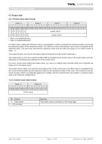
4.3 Output data 4.3.1 Preset value data format Date: 20.11.2018 Page 11 of 30 Document no. TRK 13349 FE
Open the catalog to page 11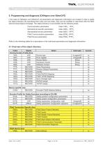
5. Programming and diagnosis (CANopen over EtherCAT) n the case of CANopen over EtherCAT, all parameters and diagnostic information are located in what is called the object directory. By specifying their index and sub-index, they can be modified or read there with the SDO (Service Data Object) message. The object directory is sub-divided into the following areas: Communication parameters Index 1000h - 1FFFh Manufacturer-specific parameters Index 2000h - 5FFFh Standardised device parameters Index 6000h - 9FFFh FSoE Communication parameters Index E000h- EFFFh FSoE Device parameters Index F000h-...
Open the catalog to page 12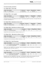
5.2 Communication parameters 5.2.1 Objekt 1000h - Device type By writing “load” (hex: 0x64616F6C) in sub-index 1, the parameters’ default values are loaded into the EEPROM and become active after power off/on. Following execution, the value is reset to “1”. Date: 20.11.2018 Page 13 of 30 Document no. TRK 13349 FE
Open the catalog to page 13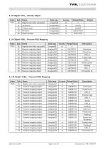
5.2.8 Objekt 1018h - Identity Object Date: 20.11.2018 Page 14 of 30 Document no. TRK 13349 FE
Open the catalog to page 14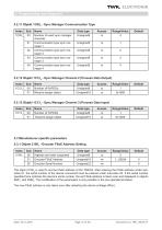
5.2.11 Objekt 1C00h - Sync Manager Communication Type The object 2100h is used to set the FSoE address of the TRK/S3. After entering the FSoE address under subindex 01, the serial number of the device concerned must be entered under sub-index 02. If the serial number specified here matches the device's serial number, the set FSoE address is taken over and displayed in objects E901h and F980h. The modification of the parameters is only possible in the pre-operiational status. The new FSoE address is only taken over after restarting the device (voltage off/on). Date: 20.11.2018 Page 15 of 30 Document...
Open the catalog to page 15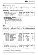
5.4 Standardised device parameters Those parameters marked with “rw” in this chapter can be set by the user. To store the parameters in a failsafe manner in the encoder’s EEPROM, the “save” command must then be executed under the object 1010h (see chapter 5.2.6) .The modification of the parameters is only possible in the pre-operiational status. 5.4.1 Objekt 6100h - Safety position configuration parameters After changing a safety parameter and writing the new checksum (object 61FFh), the parameterisation must be Date: 20.11.2018 Page 16 of 30 Document no. TRK 13349 FE
Open the catalog to page 16All TWK-ELEKTRONIK GmbH catalogs and technical brochures
 Rotary encoder TBN58/C3 manual
50 Pages
 Rotary encoder TBN58/C3
22 Pages
 Rotary encoder TBD Manual
26 Pages
 Rotary encoder TBD
12 Pages
 Rotary encoder TBE58
16 Pages
 Rotary encoder KRP - Manual
19 Pages
 Rotary encoder KRP
7 Pages
 Rotary encoder TBN58/S4 SIL2
22 Pages
 Rotary encoder TBN50/C3 manual
20 Pages
 Rotary encoder TBN50/C3
22 Pages
 Rotary encoder HBN/S3 SIL2
16 Pages
 Product range 2022
64 Pages
 Image brochure TWK
28 Pages
 Inclinometer NBA51
6 Pages
 Incremental encoder FOI
7 Pages
 Rotary encoder TBA42
16 Pages
 Rotary encoder TRA42
16 Pages
 Rotary encoder TRN58/S4 SIL2
22 Pages
 Rotary encoder TRN58/C3 manual
50 Pages
 Rotary encoder TRN58/C3
22 Pages
 Rotary encoder TRN42/S4 SIL2
22 Pages
 Manual TRN50/C3
86 Pages
 Rotary encoder TRN50/C3
22 Pages
 Rotary encoder TRN42/C3 manual
86 Pages
 Rotary encoder TRN42/C3
22 Pages
 Rotary encoder TBN42/S4 SIL2
22 Pages
 Rotary encoder TBN42/C3 manual
86 Pages
 Rotary encoder TBN42/C3
22 Pages
 Rotary encoder TRE58
16 Pages
 Rotary encoder TRT manual
40 Pages
 Rotary encoder TRT
14 Pages
 Switching cam encoder NOCE
14 Pages
 Switching cam encoder NOCA
17 Pages
 Vibration sensor NVT/S3 PLd
12 Pages
 Vibration sensor NVA
12 Pages
 Inclinometer NBN
17 Pages
 Incremental encoder TBI42
6 Pages
 Vibration sensor NVA/S3 PLd
15 Pages
 Rotary transducer PMR411
1 Page
 Rotary encoder TRT/S3 SIL2
13 Pages
 Rotary transducer VP12
1 Page
 Switching cam encoder NOCN
22 Pages
 Inclination sensor NBT manual
21 Pages
 Inclination sensor NBT
10 Pages
 Inclinometer NBA
17 Pages
 Inclinometer NBT/S3 SIL2/PLd
12 Pages
 Inclinometer NBN/S3 SIL2
13 Pages
 Rotary encoder TBE50
16 Pages
 Rotary encoder HBE
14 Pages
 Rotary encoder TRK manual
18 Pages
 Rotary encoder TRK
11 Pages
 Rotary encoder TMN50 manual
22 Pages
 Rotary encoder TMN50
6 Pages
 Rotary encoder TRK/S3 SIL2
14 Pages
 Rotary encoder TRE42
6 Pages
 Rotary encoder TRE50
6 Pages
 Rotary encoder TRA50
6 Pages
 Rotary encoder TBE42
6 Pages
 Rotary encoder TME42
6 Pages
 Rotary encoder TRD manual
26 Pages
 Rotary encoder TRD
12 Pages
 Rotary encoder TME50
6 Pages
 Rotary encoder TBN36
6 Pages
 Rotary encoder TMA50
6 Pages
 Rotary encoder TMN42 manual
22 Pages
 Rotary encoder TMN42
6 Pages
 Rotary encoder TMA42
6 Pages
 Rotary encoder TBA50
16 Pages
 Rotary encoder TBE36 manual
22 Pages
 Rotary encoder TBE36
6 Pages
 Rotary encoder TBN42
6 Pages
 Rotary encoder TBN37
8 Pages
 Rotary encoder TBA37
7 Pages
 Rotary encoder TBB50
16 Pages
 Rotary encoder PBA12
2 Pages
 Rotary encoder TBA36
6 Pages
 Rotary encoder TKA60
2 Pages
 Rotary encoder TKN46 manual
22 Pages
 Rotary encoder TKN46
7 Pages




- Incremental encoder
- Incremental rotary encoder
- Absolute rotary encoder
- Tilt sensor
- Industrial rotary encoder
- Magnetic rotary encoder
- Displacement transducer
- Linear displacement sensor
- Digital inclination sensor
- Aluminum rotary encoder
- Stainless steel rotary encoder
- Single-turn rotary encoder
- MEMS inclination sensor
- Flange rotary encoder
- Ultra-rugged rotary encoder
- Multi-axis tilt sensor
- SSI angular encoder
- Multi-turn rotary encoder
- Analog displacement transducer