- Catalogs
- TWK-ELEKTRONIK GmbH
- Rotary encoder TRD
- Company
- Products
- Catalogs
- News & Trends
- Exhibitions
Rotary encoder TRD
1 /12Pages

Rotary encoder TRD
1 /12Pages
Catalog excerpts

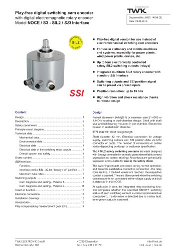
Absolute encoder TBD/TRD with PROFIBUS-DP interface Singleturn and multiturn versions Contactless, wear-free sensor system according to the Hall principle High vibration and shock resistance thanks to the robust mechanical design Measuring range: 4096 revolutions (12-bit) Protection type: IP 66, IP 69K (on request) Preset button in the connecting cap Option: Draw wire version with integrated encoder: TRD125-D Profibus characteristics Recording of the angular position and revolutions by means of Hall sensors - multiturn version with absolute transmission for up to 4096 revolutions - data output plus parameterisation and diagnosis via Profibus-DP. Robust housing manufactured from seawater-proof aluminium or stainless steel - stainless steel shaft - ball bearing with radial shaft seal - sensor circuit consisting of ASIC with Hall elements - electrical connections via the connecting cap with threaded cable connections. - Address and terminating resistors can be set in the connecting cap using DIP switches - Transmission rate of up to 12 MBaud - Reference value setting via the control system output data and preset button - Parameterisable via Profibus The absolute encoders are designed for direct connection to the PROFIBUS-DP. The interface is implemented with the SPC3 Siemens PROFIBUS controller. The protocol corresponds to DP-Slave Class 2 functionality in accordance with Profibus profile for encoders, No. 3.062, and is described in detail in the TRD 12770 user manual. The TRD is mechanicallly and electrically compatible with the electro-optical encoder CRD. The draw wire version with integrated encoder offers a very compact solution for length measurement up to 10 m. See datasheet 125-D13794 for mechnical design. TWK-ELEKTRONIK GmbH Heinrichstrasse 85
Open the catalog to page 1
Input data * ■ 4 bytes position ■ 4 bytes velocity (firmware version 1.02 or higher) Output data * ■ 4 bytes preset ASIC with HALL elements + 13.5 VDC to + 30 VDC (reverse voltage protection) < 2 W, switch on current < 250 mA Resolution: 4096 steps / 360°< (12-bit) or 8192 steps / 360°< (13-bit) 4096 revolutions Max. 25-bit ± 0.2 % (with reference to one revolution), singleturn version ± 0.1 % Binary CW / CCW < 2 ms 1000 rpm max. (optionally up to 4000 rpm) 105 rad/s2 max. 20 gcm2 < 8 Ncm (at 500 rpm) < 4 Ncm 250 N axial 250 N radial > 109 revolutions ca. 0.450 kg Electrical data ■ Sensor system:...
Open the catalog to page 2
Bus-specific data ■ Specifications: ■ Interface: ■ Data rate: ■ Station address: ■ GSD file: ■ Freeze-mode: ■ Sync-mode: ■ Automatic baud rate search: ■ Diagnosis bytes ■ User-Parameterbytes ■ Configuration options: PROFIBUS-DP-V0, slave subscriber SPC3 Siemens PROFIBUS controller Line driver according to RS 485, galvanically separated via magnetic couplers 9.6 kBaud to 12 MBaud 1 to 126 can be set using DIP switches, default value: 123 According to Specifications for PROFIBUS Device Description and Device Integration Volume 1: GSD PNO-Order No: 2.122 Is supported Is supported Is supported Class...
Open the catalog to page 3
Principle circuit diagram Connecting cap ZKD The cap is listed and supplied as a separate order item. It can be separated from the absolute encoder for setting purposes by releasing two screws. Connection terminal 1: Connection terminal 2: Date: 07.02.2017 Page 4 of 12 Document no. TRD 11868 ME
Open the catalog to page 4
Absolute encoder TBD/TRDElectrical connection Status-LEDs: Date: 07.02.2017 Page 5 of 12 Document no. TRD 11868 ME
Open the catalog to page 5
Order number Absolute encoder standard version Electrical and / or mechanical variants * 01 Standard 02 Compatible with the encoder model KRD D PROFIBUS-DP-V0 Electrical connection: Z Connecting cap Profil: C2 Class 2 according to encoder profile No. 3.062 Measuring range: 4096 Revolutions 10 Length in meter for draw wire version. Possible values: 6 and 10 Output code: R Binary Resolution: 4096 Steps / 360° or at draw wire: steps / drum circumference (248 mm) 8192 Housing material: A Aluminium S Stainless steel 1.4305 V Stainless steel 1.4404 Flange: K Clamped flange, shaft 10 mm with flat KF...
Open the catalog to page 6
Accessories (to be ordered separately) ■ Documentation on CD TWK-CD-01 CD-ROM with documentation, device description file, bitmap and example programme Folding bellows coupling, large, see data sheet BKK11840 Folding bellows coupling, small, see data sheet BKM11995 Clamp coupling, see data sheet KK12301 ■ Couplings BKK BKM KK14S ■ Measuring gear ZRS Play compensating measuring gear ZRS11877 ■ Torque plate ZMS See data sheet ZMS12939 ■ Further installation accessories and securing clamps are available according to data sheet MZ10111 . Documentation, GSD file, etc. The following documents plus...
Open the catalog to page 7
Absolute encoder TBD/TRD Installation drawing Standard design Design form 58 with clamped flange, Order name: TRD58-KA4096R4096C2ZD01 Shaft ø 10 mm ca. 5 Access to the preset button Shaft sealing ring * singleturn version 14 mm shorter n Optional: Shaft "P" groove and parallel key 3 Blind plug Diagnostic LED`s: See table on page 5
Open the catalog to page 8
Absolute encoder TBD/TRD Installation drawing Other possible design forms Design form 58 with synchroniser flange, Order name: TRD58-SA4096R4096C2ZD01 Shaft ø 6 mm 3 Access to the preset button Shaft sealing ring * singleturn version 14 mm shorter
Open the catalog to page 9
Absolute encoder TBD/TRD Installation drawing Design form 65 with synchroniser flange, Order name: TRD65-SA4096R4096C2ZD01 Shaft ø 12 mm Access to the preset button Shaft sealing ring * singleturn version 14 mm shorter n Optional: Shaft "P" groove and parallel key
Open the catalog to page 10
Absolute encoder TBD/TRD Installation drawing Design form 58 with synchroniser flange and campled shaft, Order name: TRD58-SRA4096R4096C2ZD01 Shaft ø 12 mm (other shaft diameters on request) Access to the preset button Clamped shaft Di = 12 H7 Insertion: 16 mm EMC screw connections M12x1.5 EMC screw connections M16x1.5 Shaft sealing ring 42 ±0.1 Clamp ring (Aluminium) (in scope of delivery) Maximum shaft length circulation of the torque support arm = 23,2 mm +0,2 mm (as shown) PA locking washer Torque support arm (please order separatly) Reducing bush (please order separatly) Height adapter *...
Open the catalog to page 11All TWK-ELEKTRONIK GmbH catalogs and technical brochures
 Rotary encoder TBN58/C3 manual
50 Pages
 Rotary encoder TBN58/C3
22 Pages
 Rotary encoder TBD Manual
26 Pages
 Rotary encoder TBD
12 Pages
 Rotary encoder TBE58
16 Pages
 Rotary encoder KRP - Manual
19 Pages
 Rotary encoder KRP
7 Pages
 Rotary encoder TBN58/S4 SIL2
22 Pages
 Rotary encoder TBN50/C3 manual
20 Pages
 Rotary encoder TBN50/C3
22 Pages
 Rotary encoder HBN/S3 SIL2
16 Pages
 Product range 2022
64 Pages
 Image brochure TWK
28 Pages
 Inclinometer NBA51
6 Pages
 Incremental encoder FOI
7 Pages
 Rotary encoder TBA42
16 Pages
 Rotary encoder TRA42
16 Pages
 Rotary encoder TRN58/S4 SIL2
22 Pages
 Rotary encoder TRN58/C3 manual
50 Pages
 Rotary encoder TRN58/C3
22 Pages
 Rotary encoder TRN42/S4 SIL2
22 Pages
 Manual TRN50/C3
86 Pages
 Rotary encoder TRN50/C3
22 Pages
 Rotary encoder TRN42/C3 manual
86 Pages
 Rotary encoder TRN42/C3
22 Pages
 Rotary encoder TBN42/S4 SIL2
22 Pages
 Rotary encoder TBN42/C3 manual
86 Pages
 Rotary encoder TBN42/C3
22 Pages
 Rotary encoder TRE58
16 Pages
 Rotary encoder TRT manual
40 Pages
 Rotary encoder TRT
14 Pages
 Switching cam encoder NOCE
14 Pages
 Switching cam encoder NOCA
17 Pages
 Vibration sensor NVT/S3 PLd
12 Pages
 Vibration sensor NVA
12 Pages
 Inclinometer NBN
17 Pages
 Incremental encoder TBI42
6 Pages
 Vibration sensor NVA/S3 PLd
15 Pages
 Rotary transducer PMR411
1 Page
 Rotary encoder TRT/S3 SIL2
13 Pages
 Rotary transducer VP12
1 Page
 Switching cam encoder NOCN
22 Pages
 Inclination sensor NBT manual
21 Pages
 Inclination sensor NBT
10 Pages
 Inclinometer NBA
17 Pages
 Inclinometer NBT/S3 SIL2/PLd
12 Pages
 Inclinometer NBN/S3 SIL2
13 Pages
 Rotary encoder TBE50
16 Pages
 Rotary encoder HBE
14 Pages
 Rotary encoder TRK manual
18 Pages
 Rotary encoder TRK
11 Pages
 Rotary encoder TMN50 manual
22 Pages
 Rotary encoder TMN50
6 Pages
 Rotary encoder TRK/S3 SIL2
14 Pages
 Rotary encoder TRE42
6 Pages
 Rotary encoder TRE50
6 Pages
 Rotary encoder TRA50
6 Pages
 Rotary encoder TBE42
6 Pages
 Rotary encoder TME42
6 Pages
 Rotary encoder TRD manual
26 Pages
 Rotary encoder TME50
6 Pages
 Rotary encoder TBN36
6 Pages
 Rotary encoder TMA50
6 Pages
 Rotary encoder TMN42 manual
22 Pages
 Rotary encoder TMN42
6 Pages
 Rotary encoder TMA42
6 Pages
 Rotary encoder TBA50
16 Pages
 Rotary encoder TBE36 manual
22 Pages
 Rotary encoder TBE36
6 Pages
 Rotary encoder TBN42
6 Pages
 Rotary encoder TBN37
8 Pages
 Rotary encoder TBA37
7 Pages
 Rotary encoder TBB50
16 Pages
 Rotary encoder PBA12
2 Pages
 Rotary encoder TBA36
6 Pages
 Rotary encoder TKA60
2 Pages
 Rotary encoder TKN46 manual
22 Pages
 Rotary encoder TKN46
7 Pages


- SARRALLE rotary encoder
- SARRALLE incremental encoder
- SARRALLE incremental rotary encoder
- SARRALLE absolute rotary encoder
- SARRALLE inclinometer
- SARRALLE magnetic rotary encoder
- Industrial rotary encoder
- Displacement transducer
- Linear displacement sensor
- SARRALLE digital inclinometer
- SARRALLE aluminum rotary encoder
- SARRALLE stainless steel rotary encoder
- SARRALLE single-turn rotary encoder
- MEMS inclination sensor
- Flange rotary encoder
- Multi-axis tilt sensor
- SARRALLE ultra-rugged rotary encoder
- SSI angular encoder
- SARRALLE multi-turn rotary encoder
- Analog displacement transducer