
- Catalogs
- TWK-ELEKTRONIK GmbH
- Rotary encoder TRD manual

Rotary encoder TRD manual

Rotary encoder TRD manual
- This manual is for rotary encoders with a PROFIsafe interface, intended for qualified electricians. Devices must be protected from mechanical damage and operated within specified limits.
Encoders connect directly to PROFIBUS-DP using the SPC3 Siemens controller, adhering to DP-Slave Class 2 functionality.
Installation Instructions for PROFIBUS-DP - RS 485- Network topology is a linear bus with terminating resistors. Shielded, twisted pair cables are required. Up to 32 stations per segment without repeaters, extendable to 126 with repeaters. Transmission length varies with baud rate, maxing at 1200 meters at lower speeds.
- The connecting cap facilitates easy connection and replacement of the encoder, including DIP switches for setting addresses and terminating resistors.
- Encoders are classified into Class 1 and Class 2, with Class 2 allowing parameterization via the bus. Configurations include options for 32-bit input/output and velocity data.
- Data exchange involves transmitting input data from devices to the master and output data from the master to slave devices. Actual position values can be output in 16- or 32-bit formats, with velocity values available in certain configurations. Setting a reference value is crucial for aligning machine and encoder positions, and must be done when the encoder shaft is stationary.
Programming Parameters for Class 1/2 Encoder (DDLM_Set_Prm)
Parameterisation data consists of bus-specific data and DP slave-specific data. Bus-specific data includes station status, WD_Fact_1, WD_Fact_2, Min. station delay responder, Ident_Number, and Group_Ident. DP slave-specific data varies for Class 1 and Class 2 encoders, with Class 1 using 2 bytes and Class 2 using 22 bytes of User_Prm_Data.
Definition of Programming Parameters- Operating Mode: Defined by a logic table for Octet 9, detailing parameters like code sequence, scaling function status, velocity unit, and short diagnostic.
- Measuring Units per Revolution: Defined by Octets 10-13, with data bits specifying the resolution.
- Total Measuring Range in Units: Octets 14-17 define the total measuring steps, with internal calculations based on powers of 2.
The velocity signal calculation is based on a resolution of 4096 steps per turn, independent of programmed parameters.
Examples for ParameterisationExamples are provided for Class 1 and Class 2 encoders, detailing bus-specific data, operating status, steps per turn, and total steps.
Diagnostic Messages (DDLM_Slave_Diag)- Standard Diagnostic Information: Includes manufacturer identification and standard diagnostic information.
- Device-Related Diagnosis: Details extended diagnostic range, alarm messages, operating mode, encoder type, resolution, and measuring range.
- Manufacturer-Specific Diagnosis: Includes specific error codes and rectification methods for EEPROM, RAM, and other errors.
- Integration of TWK Profibus Encoder: Details the procedure for integrating the encoder into a Siemens S7 control system, including installation of the GSD file, selection from the hardware catalogue, and allocation of Profibus addresses.
- Example Programmes: TWK provides example programmes for working with the TWK Profibus encoder, available in both German and English. These programmes are designed for CPU315-2DP and include modules generated with the KOP/FUP/AWL Editor.
- TWKDPCL1 Project: Includes programme folders for class 1 projects, with programmes like Istwert and Diag1 for accessing position values and error handling.
The document outlines the use of OB86 and OB82 for detecting encoder failures and diagnosis requests, respectively. It describes the use of Step7 system function SFC13 to read the diagnosis range, which is 16 bytes for class 1 encoders. The Diag2 program is designed for two encoders and allows selection between 16 or 32-bit encoder inputs.
Installation of Example Programs:Prerequisites include generating a project and inserting a control system with hardware configuration. Encoders are connected to a Profibus subnetwork with specified addresses. Installation involves retrieving and dearchiving the example project files in Simatic Manager.
TWKDPCL2 Project:This class 2 project includes programs like Istwert, IstRef, Diag1, and Diag2. The IstRef program reads actual position values and sets preset values. Diag1 handles error diagnostics for class 2 encoders with a 63-byte diagnosis range.
Explanation of Example Programs:Each program folder contains a symbol table with global variables. The cyclical program involves reading actual values, setting reference values, and handling error messages from OB82 and OB86. The document details the process of copying blocks into a project and setting reference values.
Diagnostic Range and Error Handling:The diagnostic range is read via SFC13, with class 1 having 16 bytes and class 2 having 63 bytes. OB82 provides the address of the slave in its local data, and only manufacturer-specific error message bits are evaluated.
Scope of Delivery:The delivery includes an encoder with a DP interface and pin assignment. The GSD-file, complete documentation, and example programs are available online.
Appendix A: Encoder Terms:This section explains terms like measuring units per revolution, measuring range, total measuring range in units, code sequence, and preset value. It provides definitions and specifications for these parameters.
Catalog excerpts

T-series encoders with PROFIBUS interface Accompanying data sheet TRD 11868 User manual TWK-ELEKTRONIK GmbH Heinrichstrasse 85 [email protected] www.twk.de
Open the catalog to page 1
COPYRIGHT: The Operating Instructions TRD 12770 is owned by TWK-ELEKTRONIK GMBH and is protected by copyright laws and international treaty provisions. © 2013 by TWK-ELEKTRONIK GMBH POB 10 50 63 ■ 40041 Dusseldorf ■ Germany Tel. +49/211/63 20 67 ■ Fax +49/211/63 77 05 [email protected] ■ www.twk.de Date: 19.12.2013 page 2 of 26 document no. TRD 12770 CE
Open the catalog to page 2
Safety instructions 1. Safety instructions 1.1 Scope of validity This user manual applies exclusively to the following rotary encoders with PROFIsafe interface: 1.2 Documentation The following documents must be noted: - The owner's system-specific operating instructions - This user manual - Data sheet number TRD 11868 - The pin assignment enclosed with the device - Installation instruction TZY 10206 enclosed with the device 1.3 Proper use TWK-ELEKTRONIK GmbH's rotary encoders and linear transducers are used to record rotary and linear positions, and make their measured values available as an...
Open the catalog to page 5
General 2. General The PROFIBUS encoders are designed for direct connection to PROFIBUS-DP. The interface is implemented with the SPC3 Siemens PROFIBUS controler. The protocol corresponds to the DP-Slave Class 2 functionality in accordance with the Profibus-Profile for Encoders, No. 3.062. The first part of the user manual deals with the fundamental prerequisites for understanding the use of an encoder in the PROFIBUS DP, whilst the second part provides instructions for use with the Siemens Step7 software, including example software. For a general understanding of the PROFIBUS field bus system...
Open the catalog to page 6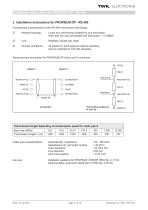
Fundamental characteristics of the RS-485 transmission technology: Linear bus, terminating resistors for bus termination Stub lines are only permissible with baud rates < 1.5 MBit/s Shielded, twisted pair cable 32 stations in each segment without repeaters Can be extended to 126 with repeaters. Wiring and bus termination for PROFIBUS-DP (9-pin sub-D connector): RxD/TxD-P (3) 220 n RxD/TxD-N (8) 390 n DGND (5) Transmission length depending on transmission speed for cable type A Cable type A specifications: Characteristic impedance: Capacitance per unit length coating: Loop resistance: Core diameter:...
Open the catalog to page 7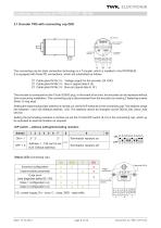
3.1 Encoder TRD with connecting cap ZKD The connecting cap for triple connection technology is a T-coupler, which is installed in the PROFIBUS. It is equipped with three PG connections, which are subdivided as follows: □ Cable gland M12x1.5 □ Cable gland M16x1.5 □ Cable gland M16x1.5 Voltage supply for the encoder (24 VDC) Bus in (signal data A, B) Bus out (signal data A‘, B‘) The encoder is connected via the 15-pin SUB-D plug. In the event of an error, the encoder can be replaced without time-consuming installation. The connecting cap is disconnected from the encoder by undoing 2 fastening screws...
Open the catalog to page 8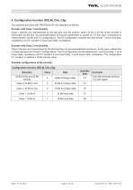
4. Configuration function (DDLM_Chk_Cfg) The absolute encoders with PROFIBUS-DP are classified as follows: Encoder with Class 1 functionality Class 1 devices are characterised by the fact that only the position value (16 bit or 32 bit) of the encoder is transmitted via the bus. No parameterisation of encoder parameters is carried out. In this case, a distinction is made between the D0 and D1 configurations. The D0 configuration contains the data format: 1 word input data, consistency and D1 contains 2 word input data, consistency. Encoder with Class 2 functionality Class 2 devices are characterised...
Open the catalog to page 9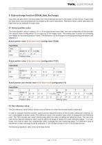
5. Data exchange function (DDLM_Data_Exchange) Input data are data which are transmitted from the peripheral devices to the master or into the bus. Output data are data which are transmitted from the master to the slave subscribers. Reference value control (see below) is listed here as an example of output data. 5.1 Actual position value The actual position value is output in 16- or 32-bit data format (input data), also see configuration of the encoder. The velocity value (configuration F3) is output as 32 bit integer value. The leading sign is positiv for increasing and negativ for decreasing...
Open the catalog to page 10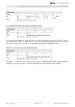
After bit 31 = 0 has been reset, the absolute encoder operates in normal operating mode. The resulting offset is saved in the encoders non volatile memory an can be read out with the diagnoctic data., (chapter 7). Date: 19.12.2013 page 11 of 26 document no. TRD 12770 CE
Open the catalog to page 11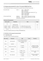
The parameterisation data are comprised from bus-specific data and DP slave-specific data. Bus-specific data: Octet 1-7 Octet 1 - Station status Octet 2 - WD_Fact_1 Octet 3 - WD_Fact_2 Octet 4 - Min. station delay responder (min TSDR) Octet 5 - Ident_Number Octet 6 - Ident_Number Octet 7 - Group_Ident Octet 8-9 Class 1 encoder ( 2 byte User_Prm_Data) Octet 8-29 Class 2 encoder (22 byte User_Prm_Data) Date: 19.12.2013 page 12 of 26 document no. TRD 12770 CE
Open the catalog to page 12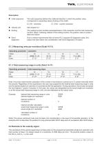
■ Code sequence: The code sequence defines the rotational direction in which the position value corresponds to ascending values (looking at the shaft). □ CW - clockwise □ CCW - counter clockwise The scaling function enables parameterisation of the resolution and the total measuring function: steps. Following release of the scaling function, the position value is recalcu lated and output. Due to market requirements that not every PLC supports 63 diagnostic bytes, this aspect has been taken into consideration with short diagnostic (16 bytes). 6.1.2 Measuring units per revolution (Octet 10-13) Note:...
Open the catalog to page 13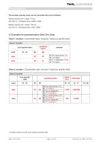
The encoder velocity value can be converted into rpm as follows: Setting velocity unit = steps / 10 ms: rpm [min-1] = indicated value x 6000 / 4096 Setting velocity unit = steps / 100 ms: rpm [min-1] = indicated value x 600 / 4096 6.3 Examples for parameterisation (User_Prm_Data) Class 1 encoder ( 9 parameter bytes, inclusive 7 bytes bus specific data)1 Date: 19.12.2013 page 14 of 26 document no. TRD 12770 CE example contains only DP-slave specific parameter data
Open the catalog to page 14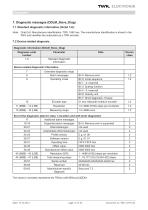
7. Diagnostic messages (DDLM_Slave_Diag) 7.1 Standard diagnostic information (Octet 1-6): Note: Octet 5,6: Manufacturer identification: TRD: 1962 hex. The manufacturer identification is stored in the PNO and identifies the subscriber as a TWK encoder. The values in brackets represents the TRDxx-xx8192RxxxxC2ZD01. Date: 19.12.2013 page 15 of 26 document no. TRD 12770 CE
Open the catalog to page 15All TWK-ELEKTRONIK GmbH catalogs and technical brochures
 Rotary encoder TBN58/C3 manual
50 Pages
 Rotary encoder TBN58/C3
22 Pages
 Rotary encoder TBD Manual
26 Pages
 Rotary encoder TBD
12 Pages
 Rotary encoder TBE58
16 Pages
 Rotary encoder KRP - Manual
19 Pages
 Rotary encoder KRP
7 Pages
 Rotary encoder TBN58/S4 SIL2
22 Pages
 Rotary encoder TBN50/C3 manual
20 Pages
 Rotary encoder TBN50/C3
22 Pages
 Rotary encoder HBN/S3 SIL2
16 Pages
 Product range 2022
64 Pages
 Image brochure TWK
28 Pages
 Inclinometer NBA51
6 Pages
 Incremental encoder FOI
7 Pages
 Rotary encoder TBA42
16 Pages
 Rotary encoder TRA42
16 Pages
 Rotary encoder TRN58/S4 SIL2
22 Pages
 Rotary encoder TRN58/C3 manual
50 Pages
 Rotary encoder TRN58/C3
22 Pages
 Rotary encoder TRN42/S4 SIL2
22 Pages
 Manual TRN50/C3
86 Pages
 Rotary encoder TRN50/C3
22 Pages
 Rotary encoder TRN42/C3 manual
86 Pages
 Rotary encoder TRN42/C3
22 Pages
 Rotary encoder TBN42/S4 SIL2
22 Pages
 Rotary encoder TBN42/C3 manual
86 Pages
 Rotary encoder TBN42/C3
22 Pages
 Rotary encoder TRE58
16 Pages
 Rotary encoder TRT manual
40 Pages
 Rotary encoder TRT
14 Pages
 Switching cam encoder NOCE
14 Pages
 Switching cam encoder NOCA
17 Pages
 Vibration sensor NVT/S3 PLd
12 Pages
 Vibration sensor NVA
12 Pages
 Inclinometer NBN
17 Pages
 Incremental encoder TBI42
6 Pages
 Vibration sensor NVA/S3 PLd
15 Pages
 Rotary transducer PMR411
1 Page
 Rotary encoder TRT/S3 SIL2
13 Pages
 Rotary transducer VP12
1 Page
 Switching cam encoder NOCN
22 Pages
 Inclination sensor NBT manual
21 Pages
 Inclination sensor NBT
10 Pages
 Inclinometer NBA
17 Pages
 Inclinometer NBT/S3 SIL2/PLd
12 Pages
 Inclinometer NBN/S3 SIL2
13 Pages
 Rotary encoder TBE50
16 Pages
 Rotary encoder HBE
14 Pages
 Rotary encoder TRK manual
18 Pages
 Rotary encoder TRK
11 Pages
 Rotary encoder TMN50 manual
22 Pages
 Rotary encoder TMN50
6 Pages
 Rotary encoder TRK/S3 SIL2
14 Pages
 Rotary encoder TRE42
6 Pages
 Rotary encoder TRE50
6 Pages
 Rotary encoder TRA50
6 Pages
 Rotary encoder TBE42
6 Pages
 Rotary encoder TME42
6 Pages
 Rotary encoder TRD
12 Pages
 Rotary encoder TME50
6 Pages
 Rotary encoder TBN36
6 Pages
 Rotary encoder TMA50
6 Pages
 Rotary encoder TMN42 manual
22 Pages
 Rotary encoder TMN42
6 Pages
 Rotary encoder TMA42
6 Pages
 Rotary encoder TBA50
16 Pages
 Rotary encoder TBE36 manual
22 Pages
 Rotary encoder TBE36
6 Pages
 Rotary encoder TBN42
6 Pages
 Rotary encoder TBN37
8 Pages
 Rotary encoder TBA37
7 Pages
 Rotary encoder TBB50
16 Pages
 Rotary encoder PBA12
2 Pages
 Rotary encoder TBA36
6 Pages
 Rotary encoder TKA60
2 Pages
 Rotary encoder TKN46 manual
22 Pages
 Rotary encoder TKN46
7 Pages




- Incremental encoder
- Incremental rotary encoder
- Absolute rotary encoder
- Tilt sensor
- Industrial rotary encoder
- Magnetic rotary encoder
- Displacement transducer
- Linear displacement sensor
- Digital inclination sensor
- Aluminum rotary encoder
- Stainless steel rotary encoder
- Single-turn rotary encoder
- MEMS inclination sensor
- Flange rotary encoder
- Ultra-rugged rotary encoder
- Multi-axis tilt sensor
- SSI angular encoder
- Multi-turn rotary encoder
- Analog displacement transducer