- Catalogs
- TWK-ELEKTRONIK GmbH
- Rotary encoder TBE36 manual
- Company
- Products
- Catalogs
- News & Trends
- Exhibitions
Rotary encoder TBE36 manual
1 /22Pages

Rotary encoder TBE36 manual
1 /22Pages
Catalog excerpts
T Series Encoders with CANopen Interface User Manual TWK-ELEKTRONIK GmbH · PB. 10 50 63 · D-40041 Düsseldorf
Open the catalog to page 1
COPYRIGHT: The TXN 11551 operating instructions are owned by TWK-ELEKTRONIK GMBH and are protected by copyright laws and international treaty provisions. © 2009 by TWK-ELEKTRONIK GMBH POB 10 50 63 ■ 40041 Dusseldorf ■ Germany Tel. +49/211 /63 20 67 ■ Fax +49/211 /63 77 05 [email protected] ■ www.twk.de
Open the catalog to page 2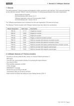
1. General The electromagnetic T Series encoders are designed for direct connection to the CAN bus. This is achieved internally via the CAN bus controller T89C51 CC02 SO 28 (Atmel). The following specifications have been implemented: Device Profile for Encoders CiA Draft Standard 406, Version 3.0 /1/ CANopen Application Layer and Communication Profile CiA Draft Standard 301, Version 4.02 /2/ The CANopen specifications can be obtained from the user organisation CiA (www.can-cia.org). The following T Series encoders with CANopen interface have been taken into consideration: 2. CANopen features...
Open the catalog to page 5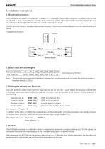
3. Installation instructions 3.1 Electrical connection CiA Draft Recommendation Proposal 303-1, Version 1.1.1 CANopen Cabling and Connector Pin Assignment /3/ must be adhered to when connecting the encoder. This particularly applies with regard to the terminal resistors, the lead characteristics, the length of the branch lines and the transmission length. The bus terminal resistors must be implemented internally. The precise connector assignment is enclosed with each device. Principle bus structure: 3.2 Baud rates and lead lengths Note: The encoder has no galvanic separation between the supply...
Open the catalog to page 6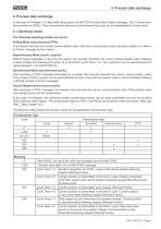
4. Process data exchange In the case of CANopen, I/O data traffic takes place via the PDO (Process Data Object) message. The T Series encoders provide two PDOs. Their transmission behaviour (transmission type) can be set independently of each other. 4.1 Operating modes The following operating modes can be set: Polling Mode (asynchronous-RTR): The encoder transmits the current, actual position value, after the current position value has been polled via a „Remo-te Frame“ message by the master. Asynchronous Mode (cyclic / acyclic): Without being requested to do so by the master, the encoder transmits...
Open the catalog to page 7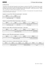
4. Process data exchange 4.2 Data format The definition of the output data (mapping) and their depiction is identical for both PDOs. The position value is output in steps and, in the case of the variant with speed signal, the speed value is output in steps per 100 ms. The position and speed value can also be called up in the object directory under indices 6004h - Position value and 2010h - Speed value. The position and speed values are depicted in Intel format. The following tables show encoders with 13 bits single turn resolution. For encoders with 12 bit resolution the positi-onvalue is one...
Open the catalog to page 8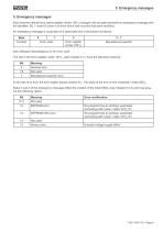
5. Emergency messages Each time the internal error status register (Index 1001 h) changes, the encoder transmits an emergency message with the identifier: 80h + node ID (even if an error which has occurred has been rectified). An emergency message is comprised of 8 data bytes and is structured as follows:
Open the catalog to page 9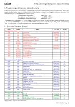
6. Programming and diagnosis (object directory) 6. Programming and diagnosis (object directory) In the case of CANopen, all parameters and diagnostic information are contained in the object directory. There, they may be changed and/or read with the SDO (Service Data Object) message, specifying their index and sub-index. The object directory is sub-divided into the following areas: Communication parameters Index 1000h - 1FFFh Manufacturer-specific parameters Index 2000h - 5FFFh Standardised device parameters Index 6000h - 9FFFh Those parameters marked with “rw” in this chapter can be set by the...
Open the catalog to page 10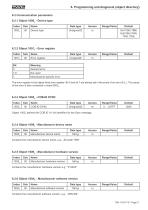
6.2 Communication parameters 6.2.1 Object 1000h - Device type Contains the manufacturer software version, e.g.: „TBN Std“
Open the catalog to page 11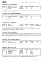
6. Programming and diagnosis (object directory) 6.2.7 Object 1010h - Store parameters The information in object 1018h (also see Chapter 3.3) is required to use the Layer Setting Service (LSS, /5/).
Open the catalog to page 12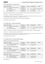
6.2.13 Object 1800h - First transmit PDO
Open the catalog to page 13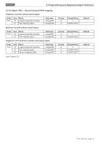
6. Programming and diagnosis (object directory)
Open the catalog to page 14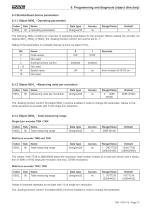
6.3 Standardised device parameters 6.3.1 Object 6000h - Operating parameters Values in brackets represent an encoder with 13 bit single turn resolution. The „Scaling function control" bit (object 6000h) must be enabled in order to change the parameter.
Open the catalog to page 15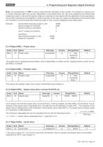
6. Programming and diagnosis (object directory) Note: For parametration of TRN it must be noted that the calculation of the number of revolutions is carried out in 2n powers internally within the encoder. Regardless of this requirement, the user may programme the desired total measuring range in units and the desired single turn resolution in accordance with the application. During calculation, the encoder accesses the next highest 2n power if required. In this case, the values are designated as the actual single turn resolution or as the actual total measuring range in units, and are displayed...
Open the catalog to page 16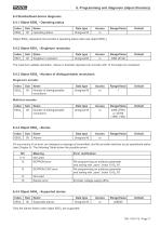
6.4 Standardised device diagnosis 6.4.1 Object 6500h - Operating status Only the alarms listed under object 6503h are supported.
Open the catalog to page 17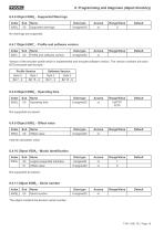
6. Programming and diagnosis (object directory) 6.4.6 Object 6506h - Supported Warnings The object contains the device‘s serial number.
Open the catalog to page 18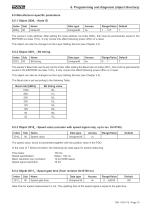
6.5 Manufacturer-specific parameters 6.5.1 Object 2000h - Node ID Gate time for speed measurement in ms. The updating time of the speed signal is equal to the gate time.
Open the catalog to page 19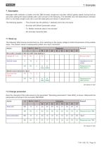
7. Examples Message traffic between a master and the TBN encoder (single-turn encoder without speed signal) during boot-up and when setting the slave address with LSS is shown in the following. The identifier (ID), the transmission direction (Rx/Tx), the Data Length Code (DLC) and the data bytes are shown in tabular form. The following applies: - The encoder has the address 1 (default) and is the only slave - Encoder with default parameter values - Tx: Master transmits data to the encoder - Rx: Encoder transmits data 7.1 Boot-up The following Table shows encoder boot-up, from switching on the...
Open the catalog to page 20All TWK-ELEKTRONIK GmbH catalogs and technical brochures
 Rotary encoder TBN58/C3 manual
50 Pages
 Rotary encoder TBN58/C3
22 Pages
 Rotary encoder TBD Manual
26 Pages
 Rotary encoder TBD
12 Pages
 Rotary encoder TBE58
16 Pages
 Rotary encoder KRP - Manual
19 Pages
 Rotary encoder KRP
7 Pages
 Rotary encoder TBN58/S4 SIL2
22 Pages
 Rotary encoder TBN50/C3 manual
20 Pages
 Rotary encoder TBN50/C3
22 Pages
 Rotary encoder HBN/S3 SIL2
16 Pages
 Product range 2022
64 Pages
 Image brochure TWK
28 Pages
 Inclinometer NBA51
6 Pages
 Incremental encoder FOI
7 Pages
 Rotary encoder TBA42
16 Pages
 Rotary encoder TRA42
16 Pages
 Rotary encoder TRN58/S4 SIL2
22 Pages
 Rotary encoder TRN58/C3 manual
50 Pages
 Rotary encoder TRN58/C3
22 Pages
 Rotary encoder TRN42/S4 SIL2
22 Pages
 Manual TRN50/C3
86 Pages
 Rotary encoder TRN50/C3
22 Pages
 Rotary encoder TRN42/C3 manual
86 Pages
 Rotary encoder TRN42/C3
22 Pages
 Rotary encoder TBN42/S4 SIL2
22 Pages
 Rotary encoder TBN42/C3 manual
86 Pages
 Rotary encoder TBN42/C3
22 Pages
 Rotary encoder TRE58
16 Pages
 Rotary encoder TRT manual
40 Pages
 Rotary encoder TRT
14 Pages
 Switching cam encoder NOCE
14 Pages
 Switching cam encoder NOCA
17 Pages
 Vibration sensor NVT/S3 PLd
12 Pages
 Vibration sensor NVA
12 Pages
 Inclinometer NBN
17 Pages
 Incremental encoder TBI42
6 Pages
 Vibration sensor NVA/S3 PLd
15 Pages
 Rotary transducer PMR411
1 Page
 Rotary encoder TRT/S3 SIL2
13 Pages
 Rotary transducer VP12
1 Page
 Switching cam encoder NOCN
22 Pages
 Inclination sensor NBT manual
21 Pages
 Inclination sensor NBT
10 Pages
 Inclinometer NBA
17 Pages
 Inclinometer NBT/S3 SIL2/PLd
12 Pages
 Inclinometer NBN/S3 SIL2
13 Pages
 Rotary encoder TBE50
16 Pages
 Rotary encoder HBE
14 Pages
 Rotary encoder TRK manual
18 Pages
 Rotary encoder TRK
11 Pages
 Rotary encoder TMN50 manual
22 Pages
 Rotary encoder TMN50
6 Pages
 Rotary encoder TRK/S3 SIL2
14 Pages
 Rotary encoder TRE42
6 Pages
 Rotary encoder TRE50
6 Pages
 Rotary encoder TRA50
6 Pages
 Rotary encoder TBE42
6 Pages
 Rotary encoder TME42
6 Pages
 Rotary encoder TRD manual
26 Pages
 Rotary encoder TRD
12 Pages
 Rotary encoder TME50
6 Pages
 Rotary encoder TBN36
6 Pages
 Rotary encoder TMA50
6 Pages
 Rotary encoder TMN42 manual
22 Pages
 Rotary encoder TMN42
6 Pages
 Rotary encoder TMA42
6 Pages
 Rotary encoder TBA50
16 Pages
 Rotary encoder TBE36
6 Pages
 Rotary encoder TBN42
6 Pages
 Rotary encoder TBN37
8 Pages
 Rotary encoder TBA37
7 Pages
 Rotary encoder TBB50
16 Pages
 Rotary encoder PBA12
2 Pages
 Rotary encoder TBA36
6 Pages
 Rotary encoder TKA60
2 Pages
 Rotary encoder TKN46 manual
22 Pages
 Rotary encoder TKN46
7 Pages


- SARRALLE rotary encoder
- SARRALLE incremental encoder
- SARRALLE incremental rotary encoder
- SARRALLE absolute rotary encoder
- SARRALLE inclinometer
- SARRALLE magnetic rotary encoder
- Industrial rotary encoder
- Displacement transducer
- Linear displacement sensor
- SARRALLE digital inclinometer
- SARRALLE aluminum rotary encoder
- SARRALLE stainless steel rotary encoder
- SARRALLE single-turn rotary encoder
- MEMS inclination sensor
- Flange rotary encoder
- Multi-axis tilt sensor
- SARRALLE ultra-rugged rotary encoder
- SSI angular encoder
- SARRALLE multi-turn rotary encoder
- Analog displacement transducer