
- Catalogs
- TWK-ELEKTRONIK GmbH
- Rotary encoder KRP - Manual

Rotary encoder KRP - Manual

Rotary encoder KRP - Manual
- Scope: Applicable to KRPxx-xxxxxxxR4096C1xP01 rotary encoders with Ethernet/IP interface.
- Documentation: Includes system-specific instructions, manual, data sheet KRP13386, connection assignment, and assembly instructions TZY10206.
- Proper Use: Designed for registering angular or linear positions and providing electrical output signals. Must be connected to downstream electronics.
- Commissioning: Only by specialist electricians, within specified limits, and with all connections checked.
- The KRP encoders connect directly to Ethernet/IP systems, delivering 24- or 25-bit position values and 16-bit velocity signals.
- General: Follow Ethernet/IP physical layer data; max cable length 100m; integrated switch allows various topologies.
- Electrical Connection: Separate connectors for supply and Ethernet; ports are interchangeable due to integrated switch.
- Setting the Address: IP address assigned via BOOTP/DHCP server; process involves connecting to network, starting server, and configuring IP.
- Status LEDs: Indicate network connection, data exchange, IP availability, and errors.
- Project Planning: EDS file available for integration; example provided for Logix Designer.
- Prerequisites: Project creation in Logix Designer with Ethernet network.
- EDS File Installation: Use EDS Hardware Installation Tool to register and install the file.
- Installing the Encoder: Add new module in device catalogue, configure properties, and assign IP.
- Parameterising: Parameters transferred during connection establishment; can be changed online.
- Setting the Preset: Align machine position with encoder's absolute position by setting a reference value.
- Input Data: Configuration options for position value and velocity data.
The position value is output as a 32-bit unsigned integer in Little-Endian format, with a factory-set resolution of 8192 steps per revolution. This can be adjusted through parameterisation.
Velocity
Velocity is calculated using cyclically read position data and is expressed in steps per gate time. The gate time can be modified via parameterisation. The velocity is output as a 16-bit signed integer in Little-Endian format, with positive values indicating ascending position and negative values indicating descending position.
Parameterisation
The rotary encoder is parameterised using acyclical Explicit Messaging services or during start-up. It is crucial not to change parameterisation while the system is operational.
Rotary Encoder Parameters
- Position Value: Current position as a signed integer.
- Position Sensor Type: Indicates the type of encoder.
- Direction Counting Toggle: Sets the counting direction (clockwise or counterclockwise).
- Scaling Function Control: Enables or disables position value scaling.
- Measuring Units per Span: Sets resolution per revolution.
- Total Measuring Range: Defines the total number of steps.
- Preset Value: Sets a reference value within the step range.
- Velocity Format: Defines the unit for velocity measurement.
- Operating Status: Displays the current operating mode.
Services include resetting the encoder, reading attributes, and writing attributes.
Scope of Delivery
The delivery includes a rotary encoder with an Ethernet/IP interface and connection assignment. Additional resources such as the data sheet, manual, and EDS file are available online.
Annex A: Rotary Encoder Terms
Definitions for terms such as resolution, measuring range, total number of steps, code path, and reference value/preset are provided.
Catalog excerpts
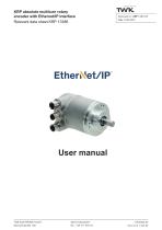
KRP absolute multiturn rotary encoder with Ethernet/IP interface Relevant data sheet KRP 13386 User manual TWK-ELEKTRONIK GmbH Bismarckstraße 108 [email protected] visit us at | twk.de
Open the catalog to page 1
SUPREME SENSORING COPYRIGHT: The Operating Instructions KRP 13387 is owned by TWK-ELEKTRONIK GMBH and is protected by copyright laws and international treaty provisions. © 2019 by TWK-ELEKTRONIK GMBH 40210 Dusseldorf ■ Germany Tel. +49/211/96117-0 ■ Fax +49/211/637705 [email protected] ■ www.twk.de Date: 16.05.2019 Page 2 of 19 Document No. KRP 13387 CE
Open the catalog to page 2
SUPREME SENSORING 1.1 Scope This user manual is valid exclusively for the following rotary encoders with Ethernet/IP interface: - KRPxx-xxxxxxxR4096C1xP01 1.2 Documentation The following documents must be observed: - The owner's system-specific operating instructions - This user manual - Data sheet number KRP13386 - The connection assignment enclosed with the device - Assembly instructions TZY10206 enclosed with the device 1.3 Proper use The TWK-ELEKTRONIK GmbH absolute encoders and linear transducers are used to register angular or linear positions and make their measured value available in...
Open the catalog to page 4
General information 2. General information The KRP absolute multiturn rotary encoders are designed for direct connection to the Industrial Ethernet System Ethernet/IP. The Ethernet/IP interface is integrated according to the following specifications: Volume 1: Common Industrial Protocol (CIP™) and Volume 2: Ethernet/IP Adaptation of CIP The specifications can be obtained from the DeviceNet/Ethernet IP user organisation ODVA (www.odva.org). Depending on configuration, the KRP delivers a 24- or 25-bit position value and also a 16-bit wide velocity signal in the unit of steps/gate time via I/O messaging....
Open the catalog to page 5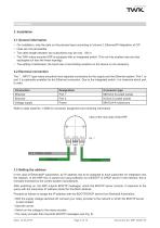
SUPREME SENSORING 3.1 General information • On installation, note the data on the physical layer according to Volume 2: Ethernet/IP Adaptation of CIP • Hubs are not permissible. • The cable length between two subscribers may be max. 100 m. • The TWK rotary encoder KRP is equipped with an integrated switch. This not only enables tree and star topologies but also the linear topology. • The setting of addresses, the baud rate or terminating resistors on the device is not necessary. 3.2 Electrical connection The " ...MP01" type rotary encoders have separate connectors for the supply and the Ethernet...
Open the catalog to page 6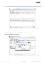
SUPREME SENSORING • Mark the line with your encoder's MAC address and click onto Add to Relation List. • Enter the desired IP address of the encoder. Fig.: 3 Date: 16.05.2019 Page 7 of 19 Document No. KRP 13387 CE
Open the catalog to page 7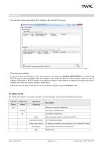
SUPREME SENSORING Installation • The encoder is then informed of its IP address in the next BOOTP query. • Then save your settings. • If you now mark the encoder in the lower window and click onto Disable BOOTP/DHCP, no further new BOOTP queries are transmitted after the voltage is next switched off/on and the encoder retains its last IP address. Otherwise, a BOOTP server must always be active in the network to supply the encoder with the IP address each time the supply voltage is switched on. • A BOOTP that has been switched off can be switched on again using the Relation List. 3.4 Status LEDs...
Open the catalog to page 8
SUPREME SENSORING 3.5 Project planning A device description file (EDS file) is available in the Internet under www.twk.de for integrating the rotary encoder into a project planning tool. File name of the EDS file: TWK_KRP_xx12.eds Project planning using the example of Logix Designer is explained in the following chapter. Date: 16.05.2019 Page 9 of 19 Document No. KRP 13387 CE
Open the catalog to page 9
Project planning with the Logix Designer 4. Project planning with the Logix Designer This chapter explains the procedure for integrating the TWK KRP rotary encoder into the Ethernet/IP network of a Compact/Control Logix control system. The documentation is based on Logix Designer Version 21.03. 4.1 Prerequisites You have created a project (here, KRP_Test) in accordance with your control system structure, including Ethernet network. (Shown here using the example of a CompactLogix 1769) 4.2 Installation of the EDS file • Under Tools, select EDS Hardware Installation Tool. • In the dialogue that...
Open the catalog to page 10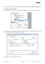
Project planning with the Logix Designer 4.3 Installing the rotary encoder Right-clicking onto the Ethernet system and selecting New Module takes you to the device catalogue (Fig. 8) In the right window, select TWK-Elektronik GmbH. The KRP rotary encoder installed using the EDS file is then shown in the bottom section. Mark this and click onto Create. This then opens the KRP properties dialogue (Fig. 9).
Open the catalog to page 11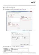
SUPREME SENSORING Project planning with the Logix Designer 4.4 Configuring the rotary encoder Assign a device name and the IP address here, and specify the I/O configuration under Module Definition (Fig. 10). The KRP's transmission cycle can be defined in the Connection tab. The following configurations are available (data formats, see Chapter 5): Date: 16.05.2019 Page 12 of 19 Document No. KRP 13387 CE
Open the catalog to page 12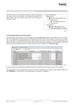
SUPREME SENSORING Project planning with the Logix Designer The KRP is now in the Ethernet network and, after downloading the project to the control system, can already be operated in its basic setting. The next chapter shows you how to change the encoder's scaling. 1769 Bus [0] 1769-L24ER-QB1B KRPJest □■■■03 Embedded I/O ^ [1] Embedded DiscreteJO Expansion I/O B-& Ethernet 1769-L24ER-QB1B KRPJest * . KRPxx-hJ8192 R4096 CIkPxx KRP_1 4.5 Parameterising the rotary encoder The Ethernet/IP rotary encoder is parameterised via the connect path during control system start-up. In this process, the configuration...
Open the catalog to page 13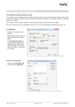
SUPREME SENSORING Project planning with the Logix Designer 4.6 Setting the preset (reference value) It is possible to set a reference value to align a machine position value with the absolute position of the rotary encoder. On setting the reference value, an offset is generated and stored in the encoder, where it is protected against zero voltage. The reference value is set by writing the Preset Value parameter in the Position Sensor Object. This can be carried out e.g. via RSNetworx (see Fig. 13) or from the application programme (as of Fig. 14). ■ Class Instance Editor - [Node 192.168.20.11]...
Open the catalog to page 14All TWK-ELEKTRONIK GmbH catalogs and technical brochures
 Rotary encoder TBN58/C3 manual
50 Pages
 Rotary encoder TBN58/C3
22 Pages
 Rotary encoder TBD Manual
26 Pages
 Rotary encoder TBD
12 Pages
 Rotary encoder TBE58
16 Pages
 Rotary encoder KRP
7 Pages
 Rotary encoder TBN58/S4 SIL2
22 Pages
 Rotary encoder TBN50/C3 manual
20 Pages
 Rotary encoder TBN50/C3
22 Pages
 Rotary encoder HBN/S3 SIL2
16 Pages
 Product range 2022
64 Pages
 Image brochure TWK
28 Pages
 Inclinometer NBA51
6 Pages
 Incremental encoder FOI
7 Pages
 Rotary encoder TBA42
16 Pages
 Rotary encoder TRA42
16 Pages
 Rotary encoder TRN58/S4 SIL2
22 Pages
 Rotary encoder TRN58/C3 manual
50 Pages
 Rotary encoder TRN58/C3
22 Pages
 Rotary encoder TRN42/S4 SIL2
22 Pages
 Manual TRN50/C3
86 Pages
 Rotary encoder TRN50/C3
22 Pages
 Rotary encoder TRN42/C3 manual
86 Pages
 Rotary encoder TRN42/C3
22 Pages
 Rotary encoder TBN42/S4 SIL2
22 Pages
 Rotary encoder TBN42/C3 manual
86 Pages
 Rotary encoder TBN42/C3
22 Pages
 Rotary encoder TRE58
16 Pages
 Rotary encoder TRT manual
40 Pages
 Rotary encoder TRT
14 Pages
 Switching cam encoder NOCE
14 Pages
 Switching cam encoder NOCA
17 Pages
 Vibration sensor NVT/S3 PLd
12 Pages
 Vibration sensor NVA
12 Pages
 Inclinometer NBN
17 Pages
 Incremental encoder TBI42
6 Pages
 Vibration sensor NVA/S3 PLd
15 Pages
 Rotary transducer PMR411
1 Page
 Rotary encoder TRT/S3 SIL2
13 Pages
 Rotary transducer VP12
1 Page
 Switching cam encoder NOCN
22 Pages
 Inclination sensor NBT manual
21 Pages
 Inclination sensor NBT
10 Pages
 Inclinometer NBA
17 Pages
 Inclinometer NBT/S3 SIL2/PLd
12 Pages
 Inclinometer NBN/S3 SIL2
13 Pages
 Rotary encoder TBE50
16 Pages
 Rotary encoder HBE
14 Pages
 Rotary encoder TRK manual
18 Pages
 Rotary encoder TRK
11 Pages
 Rotary encoder TMN50 manual
22 Pages
 Rotary encoder TMN50
6 Pages
 Rotary encoder TRK/S3 SIL2
14 Pages
 Rotary encoder TRE42
6 Pages
 Rotary encoder TRE50
6 Pages
 Rotary encoder TRA50
6 Pages
 Rotary encoder TBE42
6 Pages
 Rotary encoder TME42
6 Pages
 Rotary encoder TRD manual
26 Pages
 Rotary encoder TRD
12 Pages
 Rotary encoder TME50
6 Pages
 Rotary encoder TBN36
6 Pages
 Rotary encoder TMA50
6 Pages
 Rotary encoder TMN42 manual
22 Pages
 Rotary encoder TMN42
6 Pages
 Rotary encoder TMA42
6 Pages
 Rotary encoder TBA50
16 Pages
 Rotary encoder TBE36 manual
22 Pages
 Rotary encoder TBE36
6 Pages
 Rotary encoder TBN42
6 Pages
 Rotary encoder TBN37
8 Pages
 Rotary encoder TBA37
7 Pages
 Rotary encoder TBB50
16 Pages
 Rotary encoder PBA12
2 Pages
 Rotary encoder TBA36
6 Pages
 Rotary encoder TKA60
2 Pages
 Rotary encoder TKN46 manual
22 Pages
 Rotary encoder TKN46
7 Pages




- Incremental encoder
- Incremental rotary encoder
- Absolute rotary encoder
- Tilt sensor
- Industrial rotary encoder
- Magnetic rotary encoder
- Displacement transducer
- Linear displacement sensor
- Digital inclination sensor
- Aluminum rotary encoder
- Stainless steel rotary encoder
- Single-turn rotary encoder
- MEMS inclination sensor
- Flange rotary encoder
- Ultra-rugged rotary encoder
- Multi-axis tilt sensor
- SSI angular encoder
- Multi-turn rotary encoder
- Analog displacement transducer