- Catalogs
- TWK-ELEKTRONIK GmbH
- Rotary encoder HBN/S3 SIL2
- Company
- Products
- Catalogs
- News & Trends
- Exhibitions
Rotary encoder HBN/S3 SIL2
1 /16Pages

Rotary encoder HBN/S3 SIL2
1 /16Pages
Catalog excerpts

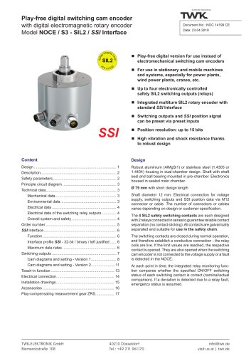
■ Robust design for rough applications with high resolution requirement such as crane technology, construction machines and special engineering ■ High vibration and shock resistance thanks to the compact mechanical design ■ Resolution < 22 bit / 360° ■ Speed signal in digits/ms with variable gate time ■ Protection type IP 66 Design - Robust housing (wall thickness 5 mm) manufactured from seawater-proof aluminium (AlMgSi1) or stainless steel (material: 1.4305 optionally 1.4404). - Position recording and evaluation are of a redundant design to implement a reliable position value and speed signal. - A network in/out module with transient filtering, voltage supply and output driver unit forms the electrical interface. - Electrical connection via two M12 connectors, 5-pin, pin and socket for bus IN / bus OUT. Function A correct mechanical connection between the customer and sensor shaft ensures that the sensor precisely detects the customer shaft's rotations. A safe position is provided by the plausibility check of two sensor systems. Detected errors are evaluated. The CAN interface outputs the validated position value and speed signal via the CANopen Safety protocol within an SRDO (Safety Relevant Data Object) using 2x2 messages (normal and inverted). The rotary encoder meets the conditions of safety level SIL2 according to IEC 61508 and performance level "d" according to EN13849. The prerequisite of safety-relevant operation is a failsafe master. TWK-ELEKTRONIK GmbH Heinrichstrasse 85 [email protected] www.twk.de
Open the catalog to page 1
Technical data Electrical data ■ Operating voltage: ■ Power consumption: ■ Resolution: ■ Code direction: ■ Reference value: ■ Accuracy: ■ Reproducibility: ■ Temperature drift: ■ CAN IC voltage rating: 9 to 36 VDC (protected against polarity reversal) < 1.8 W 16 bit (for higher resolution, please contact our technical staff) CW* or CCW** can be set 0 to (total number of steps -1) < ± 0.05 % (with reference to 360°) < ± 0.01 % (with reference to 360°) < 0.1 % (with reference to 360° over the entire temperature range) Maximum common mode votage -7 to +12 V Maximum allowed voltage at pins ±36 V Electrical...
Open the catalog to page 2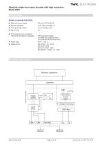
Absolute single-turn rotary encoder with high resolution Model HBN Technical data System in general and Safety Slew rate power supply: Time of storage cycles: Time between error recognition and alarm (emergency message): 100 ms (power supply) 5 s (RAM test, single bit error) 2 s (ROM test during setup time) Principle circuit diagram Sensor systems Galvanic separation Digital isolator Switching power supply Voltage monitoring
Open the catalog to page 3
Interface according to the following specifications CiA DS301 CANopen Application Layer and Communication Profile, Version 4.1 EN 50325-5 (CIA DS304) CANopen Framework for safety-relevant communication, Version 1.0.1 CiA DS305 CANopen - Layer Setting Services and Protocol (LSS) CiA DS406 CANopen - Device Profile for Encoders, Version 4.0.1 IEC 61508 Functional safety of safety-related electrical/programmable electronic systems. Supply source for the listed CANopen specifications: CAN in Automation (CiA), Kontumazgarten 3, D-90429 Nurnberg, (E-mail: [email protected], www.can-cia.org) The...
Open the catalog to page 4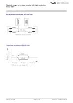
Absolute single-turn rotary encoder with high resolution Model HBN Bus termination, output level Further CANopen Subscriber TWK-CANopen Subscriber CAN-Bus CAN_L Output level according to ISO/DIS 11898 With common mode voltage = 0 V
Open the catalog to page 5
Date: 03.04.2018 Page 6 of 16 Document no. HBN 13218 GE
Open the catalog to page 6
Electrical connection ■ Two round connectors M12x1, pin and socket for bus IN/OUT, 5-pin, A-coded ■ Refer to the tables below for the connection assignments; these are also enclosed with the devices. Mating connectors (to be ordered separately) All of the mating connectors listed in the following table are M12X1, 5-pin, A-coded, with screw clamp connection, with protection type IP 67, with screening on the housing and the maximum connection cross-section is 0.75 mm2. Please note: if angled mating connectors are used, please notify us so that the device connectors can be aligned accordingly. Date:...
Open the catalog to page 7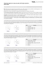
Note: This is the contact assignment for the standard version. Other versions may have a different contact assignment. In this case, please observe connection assignment TY enclosed with each device. Different M12 connector combinations or assignments are possible at the request of the customer. For the following description and pictorials is valid: Viewed looking at the PIN side of the connector installed in the HBN. There is one connector for Bus-In and Bus-Out each for the HBN. If there is only Bus-In, the female connector Bus-Out is omitted. Important: The recommended version is V1 with full...
Open the catalog to page 8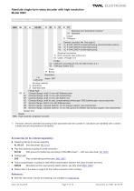
HBN 58 - K A 65,536 R S3 S V1 N 01 Electrical and mechanical variants * 01 Standard Output: N CANopen Galvanic sepration (#). See page 8: V1 -VS # CAN_GND # screening/housing (recommended version) V2 -VS = CAN_GND # screening/housing V3 -VS = CAN_GND = screening/housing Electrical connection: S M12 connector (bus in/bus out) Kx Cable, x=length in m Profile: C3 CANopen according to CIA, DS 406 revision 4.0.1 S3 CANopen Safety SIL2 Code: R Binary Resolution: Housing material: A Aluminium S Stainless steel Flange type: K Clamped flange, shaft 10 mm with flattened area KF Clamped flange, shaft 10...
Open the catalog to page 9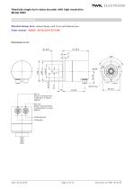
Absolute single-turn rotary encoder with high resolution Model HBN Installation drawing Standard design form: clamped flange, shaft 10 mm with flattened area Order number: HBN58 - KA 65,536 R S3 S N01 NILOS ring Bus In Sensor connector M12 5-pole pins, A-coded aligned Bus Out Sensor connector M12 5-pole socket, A-coded aligned Coding groove Coding pin
Open the catalog to page 10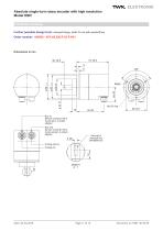
Absolute single-turn rotary encoder with high resolution Model HBN Installation drawing Further possible design form: clamped flange, shaft 10 mm with woodruff key Order number: HBN58 - KFA 65,536 R S3 S N01 NILOS ring Bus In Sensor connector M12 5-pole pins, A-coded aligned Bus Out Sensor connector M12 5-pole socket, A-coded aligned Coding groove Coding pin
Open the catalog to page 11All TWK-ELEKTRONIK GmbH catalogs and technical brochures
 Rotary encoder TBN58/C3 manual
50 Pages
 Rotary encoder TBN58/C3
22 Pages
 Rotary encoder TBD Manual
26 Pages
 Rotary encoder TBD
12 Pages
 Rotary encoder TBE58
16 Pages
 Rotary encoder KRP - Manual
19 Pages
 Rotary encoder KRP
7 Pages
 Rotary encoder TBN58/S4 SIL2
22 Pages
 Rotary encoder TBN50/C3 manual
20 Pages
 Rotary encoder TBN50/C3
22 Pages
 Product range 2022
64 Pages
 Image brochure TWK
28 Pages
 Inclinometer NBA51
6 Pages
 Incremental encoder FOI
7 Pages
 Rotary encoder TBA42
16 Pages
 Rotary encoder TRA42
16 Pages
 Rotary encoder TRN58/S4 SIL2
22 Pages
 Rotary encoder TRN58/C3 manual
50 Pages
 Rotary encoder TRN58/C3
22 Pages
 Rotary encoder TRN42/S4 SIL2
22 Pages
 Manual TRN50/C3
86 Pages
 Rotary encoder TRN50/C3
22 Pages
 Rotary encoder TRN42/C3 manual
86 Pages
 Rotary encoder TRN42/C3
22 Pages
 Rotary encoder TBN42/S4 SIL2
22 Pages
 Rotary encoder TBN42/C3 manual
86 Pages
 Rotary encoder TBN42/C3
22 Pages
 Rotary encoder TRE58
16 Pages
 Rotary encoder TRT manual
40 Pages
 Rotary encoder TRT
14 Pages
 Switching cam encoder NOCE
14 Pages
 Switching cam encoder NOCA
17 Pages
 Vibration sensor NVT/S3 PLd
12 Pages
 Vibration sensor NVA
12 Pages
 Inclinometer NBN
17 Pages
 Incremental encoder TBI42
6 Pages
 Vibration sensor NVA/S3 PLd
15 Pages
 Rotary transducer PMR411
1 Page
 Rotary encoder TRT/S3 SIL2
13 Pages
 Rotary transducer VP12
1 Page
 Switching cam encoder NOCN
22 Pages
 Inclination sensor NBT manual
21 Pages
 Inclination sensor NBT
10 Pages
 Inclinometer NBA
17 Pages
 Inclinometer NBT/S3 SIL2/PLd
12 Pages
 Inclinometer NBN/S3 SIL2
13 Pages
 Rotary encoder TBE50
16 Pages
 Rotary encoder HBE
14 Pages
 Rotary encoder TRK manual
18 Pages
 Rotary encoder TRK
11 Pages
 Rotary encoder TMN50 manual
22 Pages
 Rotary encoder TMN50
6 Pages
 Rotary encoder TRK/S3 SIL2
14 Pages
 Rotary encoder TRE42
6 Pages
 Rotary encoder TRE50
6 Pages
 Rotary encoder TRA50
6 Pages
 Rotary encoder TBE42
6 Pages
 Rotary encoder TME42
6 Pages
 Rotary encoder TRD manual
26 Pages
 Rotary encoder TRD
12 Pages
 Rotary encoder TME50
6 Pages
 Rotary encoder TBN36
6 Pages
 Rotary encoder TMA50
6 Pages
 Rotary encoder TMN42 manual
22 Pages
 Rotary encoder TMN42
6 Pages
 Rotary encoder TMA42
6 Pages
 Rotary encoder TBA50
16 Pages
 Rotary encoder TBE36 manual
22 Pages
 Rotary encoder TBE36
6 Pages
 Rotary encoder TBN42
6 Pages
 Rotary encoder TBN37
8 Pages
 Rotary encoder TBA37
7 Pages
 Rotary encoder TBB50
16 Pages
 Rotary encoder PBA12
2 Pages
 Rotary encoder TBA36
6 Pages
 Rotary encoder TKA60
2 Pages
 Rotary encoder TKN46 manual
22 Pages
 Rotary encoder TKN46
7 Pages


- SARRALLE incremental encoder
- SARRALLE incremental rotary encoder
- SARRALLE absolute rotary encoder
- SARRALLE inclinometer
- SARRALLE magnetic rotary encoder
- Industrial rotary encoder
- Displacement transducer
- Linear displacement sensor
- SARRALLE digital inclinometer
- SARRALLE aluminum rotary encoder
- SARRALLE stainless steel rotary encoder
- MEMS inclination sensor
- Flange rotary encoder
- Multi-axis tilt sensor
- SARRALLE ultra-rugged rotary encoder
- SSI angular encoder
- SARRALLE multi-turn rotary encoder
- Analog displacement transducer