- Catalogs
- TWK-ELEKTRONIK GmbH
- Magnetostrictive displacement transducer MSK manual
- Company
- Products
- Catalogs
- News & Trends
- Exhibitions
Magnetostrictive displacement transducer MSK manual
1 /17Pages

Magnetostrictive displacement transducer MSK manual
1 /17Pages
Catalog excerpts
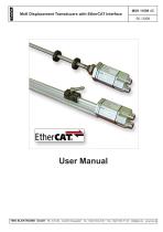
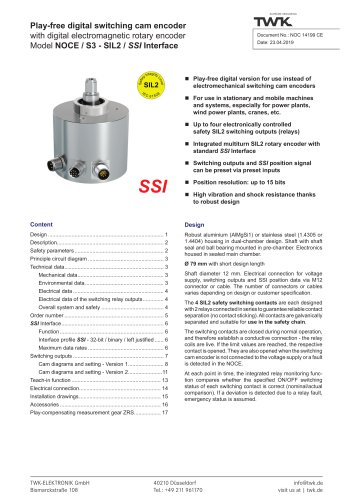
MxK Displacement Transducers with EtherCAT Interface User Manual TWK-ELEKTRONIK GmbH · PB. 10 50 63 · D-40041 Düsseldorf
Open the catalog to page 1
COPYRIGHT: The Operating Instructions MXK 11809 is owned by TWK-ELEKTRONIK GMBH and is protected by copyright laws and international treaty provisions. © 2007 by TWK-ELEKTRONIK GMBH POB 10 50 63 ■ 40041 Dusseldorf ■ Germany Tel. +49/211/63 20 67 ■ Fax +49/211/63 77 05 [email protected] ■ www.twk.de
Open the catalog to page 2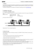
1. General 2. Installation instructions 1. General The magnetostrictive displacement transducers are designed for direct connection to the EtherCAT industrial Ethernet system. Use of the CANopen over EtherCAT message (CoE) enables parameters and diagnostic data to be handled as usual in the case of CANopen. The EtherCAT specifications can be obtained from the EtherCAT Technology Group ETG (www.ethercat.org). 2. Installation instructions 2.1 Connection via M12/M8 connector The “ ...M01” type Magnosens displacement transducers have separate connectors for the supply and the EtherCAT system. Device...
Open the catalog to page 5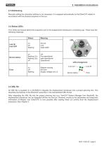
2.3 Addressing Manually setting the subscriber address is not necessary. It is assigned automatically by the EtherCAT master in accordance with the physical sequence in the bus. 2.4 Status LEDs Four LEDs are housed behind the inspection port in the displacement transducer’s connecting cap. These have the following meanings: 2.5 XML file An XML file is supplied on a CD-ROM to integrate the displacement transducer into a project planning tool. This describes the features of the EtherCAT subscriber in the standardised XML format. After integrating the XML file into the project planning tool (e.g....
Open the catalog to page 6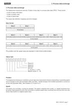
^1 3. Process data exchange 3. Process data exchange The displacement transducer transmits 10 bytes of input data in a process data object (PDO). These include: - 2 bytes of status information - 4 bytes of position data - 4 bytes of speed data The output data definition (mapping) cannot be changed. Data format The position and the speed value are depicted in Intel format (Little Endian). Reserved Reserved Reserved Error bit 0 = no error / 1 = error Magnet number (1 - 15) Position The displacement transducer’s resolution (^m per step) and measurement direction (descending or ascending signal)...
Open the catalog to page 7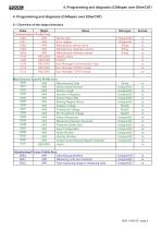
^1 4. Programming and diagnosis (CANopen over EtherCAT) 4.1 Overview of the object directory
Open the catalog to page 8
^1 4. Programming and diagnosis (CANopen over EtherCAT) 4.2 Communication parameters 4.2.1 Object 1000h - Device type
Open the catalog to page 9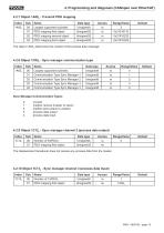
^1 4. Programming and diagnosis (CANopen over EtherCAT) 4.2.7 Object 1A00h - Transmit PDO mapping
Open the catalog to page 10
^1 4. Programming and diagnosis (CANopen over EtherCAT) 4.3 Manufacturer-specific parameters 4.3.1 Object 2000h - Manufactured date Magnet missing
Open the catalog to page 11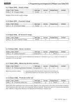
^1 4. Programming and diagnosis (CANopen over EtherCAT) 4.3.7 Object 2006h - Supply voltage Setting this buffer establishes mean value formation. Based on the values stored in the buffer, this provides a prediction of the measured value until a new, true (measured) value is received. The pre-set value of 15 has proved practicable here. Attention: A high value influences the displacement transducer’s reaction time.
Open the catalog to page 12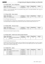
^1 4. Programming and diagnosis (CANopen over EtherCAT) 4.3.13 Object 200Ch - Save configuration
Open the catalog to page 13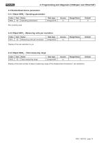
^1 4. Programming and diagnosis (CANopen over EtherCAT) 4.4 Standardised device parameters 4.4.1 Object 6000h - Operating parameters Display of the total number of steps (measuring range of the displacement transducer / set resolution).
Open the catalog to page 14
5. TwinCAT system manager 5. TwinCAT system manager 5.1 Installation of the XML file - Copy the enclosed XML file to the ..\Twincat\Io\Ethercat directory - Start the TwinCAT system manager 5.2 Online commissioning If the system is connected and capable of running, reading-in the bus structure online is the simplest option. This procedure is described here. Create a new project, mark “I/O devices” and click onto the “wand”. Confirm the following note with OK. TwinCAT should then locate your network card. Confirm this with OK.
Open the catalog to page 15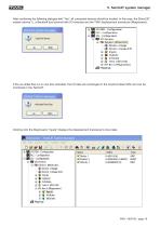
5. TwinCAT system manager After confirming the following dialogue with “Yes”, all connected devices should be located. In this case, the EtherCAT master (device 1), a Beckhoff bus terminal with I/O modules and the TWK displacement transducer (Magnosens). If the so-called free run is now also activated, the I/O data are exchanged in the acyclical data traffic and can be monitored in the TwinCAT. Clicking onto the Magnosens “Inputs” displays the displacement transducer’s input data.
Open the catalog to page 16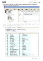
5. TwinCAT system manager If you click onto the Magnosens itself instead, the following screen’s register takes you to the displacement transducer’s configuration and parameterisation. The CoE online register accesses the parameter and diagnostic data. All parameters identified with “RW” can be changed. The description of the parameters can be found in Chapter 4. Do not forget to subsequently save the parameters in a failsafe manner via parameter 200Ch.
Open the catalog to page 17All TWK-ELEKTRONIK GmbH catalogs and technical brochures
 Rotary encoder TBN58/C3 manual
50 Pages
 Rotary encoder TBN58/C3
22 Pages
 Rotary encoder TBD Manual
26 Pages
 Rotary encoder TBD
12 Pages
 Rotary encoder TBE58
16 Pages
 Rotary encoder KRP - Manual
19 Pages
 Rotary encoder KRP
7 Pages
 Rotary encoder TBN58/S4 SIL2
22 Pages
 Rotary encoder TBN50/C3 manual
20 Pages
 Rotary encoder TBN50/C3
22 Pages
 Rotary encoder HBN/S3 SIL2
16 Pages
 Product range 2022
64 Pages
 Image brochure TWK
28 Pages
 Inclinometer NBA51
6 Pages
 Incremental encoder FOI
7 Pages
 Rotary encoder TBA42
16 Pages
 Rotary encoder TRA42
16 Pages
 Rotary encoder TRN58/S4 SIL2
22 Pages
 Rotary encoder TRN58/C3 manual
50 Pages
 Rotary encoder TRN58/C3
22 Pages
 Rotary encoder TRN42/S4 SIL2
22 Pages
 Manual TRN50/C3
86 Pages
 Rotary encoder TRN50/C3
22 Pages
 Rotary encoder TRN42/C3 manual
86 Pages
 Rotary encoder TRN42/C3
22 Pages
 Rotary encoder TBN42/S4 SIL2
22 Pages
 Rotary encoder TBN42/C3 manual
86 Pages
 Rotary encoder TBN42/C3
22 Pages
 Rotary encoder TRE58
16 Pages
 Rotary encoder TRT manual
40 Pages
 Rotary encoder TRT
14 Pages
 Switching cam encoder NOCE
14 Pages
 Switching cam encoder NOCA
17 Pages
 Vibration sensor NVT/S3 PLd
12 Pages
 Vibration sensor NVA
12 Pages
 Inclinometer NBN
17 Pages
 Incremental encoder TBI42
6 Pages
 Vibration sensor NVA/S3 PLd
15 Pages
 Rotary transducer PMR411
1 Page
 Rotary encoder TRT/S3 SIL2
13 Pages
 Rotary transducer VP12
1 Page
 Switching cam encoder NOCN
22 Pages
 Inclination sensor NBT manual
21 Pages
 Inclination sensor NBT
10 Pages
 Inclinometer NBA
17 Pages
 Inclinometer NBT/S3 SIL2/PLd
12 Pages
 Inclinometer NBN/S3 SIL2
13 Pages
 Rotary encoder TBE50
16 Pages
 Rotary encoder HBE
14 Pages
 Rotary encoder TRK manual
18 Pages
 Rotary encoder TRK
11 Pages
 Rotary encoder TMN50 manual
22 Pages
 Rotary encoder TMN50
6 Pages
 Rotary encoder TRK/S3 SIL2
14 Pages
 Rotary encoder TRE42
6 Pages
 Rotary encoder TRE50
6 Pages
 Rotary encoder TRA50
6 Pages
 Rotary encoder TBE42
6 Pages
 Rotary encoder TME42
6 Pages
 Rotary encoder TRD manual
26 Pages
 Rotary encoder TRD
12 Pages
 Rotary encoder TME50
6 Pages
 Rotary encoder TBN36
6 Pages
 Rotary encoder TMA50
6 Pages
 Rotary encoder TMN42 manual
22 Pages
 Rotary encoder TMN42
6 Pages
 Rotary encoder TMA42
6 Pages
 Rotary encoder TBA50
16 Pages
 Rotary encoder TBE36 manual
22 Pages
 Rotary encoder TBE36
6 Pages
 Rotary encoder TBN42
6 Pages
 Rotary encoder TBN37
8 Pages
 Rotary encoder TBA37
7 Pages
 Rotary encoder TBB50
16 Pages
 Rotary encoder PBA12
2 Pages
 Rotary encoder TBA36
6 Pages
 Rotary encoder TKA60
2 Pages
 Rotary encoder TKN46 manual
22 Pages
 Rotary encoder TKN46
7 Pages


- SARRALLE rotary encoder
- SARRALLE incremental encoder
- SARRALLE incremental rotary encoder
- SARRALLE absolute rotary encoder
- SARRALLE inclinometer
- SARRALLE magnetic rotary encoder
- Industrial rotary encoder
- Displacement transducer
- Linear displacement sensor
- SARRALLE digital inclinometer
- SARRALLE aluminum rotary encoder
- SARRALLE stainless steel rotary encoder
- SARRALLE single-turn rotary encoder
- MEMS inclination sensor
- Flange rotary encoder
- Multi-axis tilt sensor
- SARRALLE ultra-rugged rotary encoder
- SSI angular encoder
- SARRALLE multi-turn rotary encoder
- Analog displacement transducer