
- Catalogs
- TWK-ELEKTRONIK GmbH
- Magnetostrictive displacement transducer MSE

Magnetostrictive displacement transducer MSE

Magnetostrictive displacement transducer MSE
- Measuring strokes range from 25 to 7600 mm.
- Resolution up to 1 µm and linearity less than 0.01%.
- Operating temperature range from -40°C to +75°C.
- Protection types up to IP 68, with rod version pressure stability up to 350 bar.
- Supply voltage: 24VDC with polarity reversal protection.
- Supply current: 100 mA typical.
- Repeatability: < ± 0.001%.
- Hysteresis: < 4 µm.
- Measuring frequency: 500 to 3700 Hz.
- Temperature drift: < 15 ppm/°C.
- Shock and vibration tests conform to IEC standards.
Catalog excerpts

■ Model MPE: Profile version ■ Model MSE: Rod version ■ Measuring strokes from 25 to 7600 mm ■ Contactless, robust system ■ Resolution up to 1 pm ■ Linearity < 0.01% ■ Protection types up to IP 68 ■ Operating temperature range -40°C ... +75°C ■ Rod version pressure stability up to 350 bar Structure and operation The displacement transducers operate according to the principle of run time measurement between two points of a magnetostrictive waveguide. One point is determined by a moveable position magnet, whose distance from the null point corresponds to the section to be measured. The run time of an emitted impulse is directly proportionate to this section. Conversion to a digital measuring signal takes place in the downstream electronics. The waveguide is housed in a pressure-resistant stainless steel tube or extruded profile. To the rear of this is a die-cast aluminium housing containing the electronics in SMD technology. Electrical connection is implemented via a circular connector. In the rod version, the position magnet is located in a ring, which is guided over the rod without contact. In the profile version, it is located either in a slider, which is linked to the moving part of the machine via a ball joint, or it moves as a liftable position magnet, without wear, over the profile. Standard measuring strokes: □ Up to 1000 mm in 50 mm steps □ Up to 5000 mm in 250 mm steps (profile version: MPE) □ Up to 7600 mm in 250 mm steps (rod version: MSE) Programming ex work The displacement transducer is set to its ordered variables in the factory, as follows: □ Data length □ Data format □ Resolution (ref. to order code format) □ Measuring direction (ref. to order code format) □ Position value for start of measurement □ Alarm value for error (magnet removed) □ Differential measurement □ Speed value instead of position TWK-ELEKTRONIK GmbH ■ PB. 10 50 63 ■ D-40041 Dusseldorf ■ Tel.: +49/211/63 20 67 ■ Fax: +49/211/63 77 05 ■ [email protected] ■
Open the catalog to page 1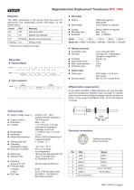
Diagnose The LEDs (green/red) in the sensor head are used for adjustment and additionally provide information on the sensor status. ■ SSI output ■ Output: Differential signal to RS422/485 ■ Data length: 25-bit (others on request) * Synchronous measurement only ■ Coding: ■ Monoflop time: ■ Baudrate: Binary (others on request) Max. 16 |js Max. 1.0 MBaud SSI-profile■ Impuls diagram data + urnn^lJTJ- ■ Mating connector: ■ Connection type: ■ Housing: ■ Contacts: ■ Cable strain relief: ■ Max. cable diameter: ■ Protection type: ■ Cable outlet: ■ Cable type: ■ Bending radius: 7-pin connector M16 Die-cast...
Open the catalog to page 2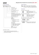
Electrical and mechanical variants* Interface: E = SSI No. of magnets (SSI: max.1) Resolution in pm: 1, 2, 5, 10, 20, 50 or 100 Signal curve: S = Positively ascending on movement from the flange towards rod end N = Descending on movement from the flange towards rod end Measuring stroke in mm Design MSE (rod): 1 = With threaded connection M 18 x 1.5 2 = With threaded connection 16 UNF % “ MPE (profile): 1 = Position slider central ball joint 2 = Position slider front ball joint 3 = Liftable position magnet Model: MPE = Profile version MSE = Rod version Rod: Sensor, nut (order position magnet separately)...
Open the catalog to page 3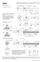
Magnetostrictive Displacement Transducers MPE / MSE Dimensions in mm Threaded connection Set null point Sensor head Position ring Measuring range Installation zone With measuring strokes of 1000 mm and over, mechanical rod support is recommended. The sensor’s fastening should be manufactured from non-magnetic materials (e.g.: brass, plastic). Note installation instruction MWA10318 on installation in magnetisable materials. Front ball joint PS02 Central ball joint PS01 Option: Cable outlet Model: MPE (profile version) Damping zone Sensor head Metal connector Installation zone Active measuring...
Open the catalog to page 4All TWK-ELEKTRONIK GmbH catalogs and technical brochures
 Rotary encoder TBN58/C3 manual
50 Pages
 Rotary encoder TBN58/C3
22 Pages
 Rotary encoder TBD Manual
26 Pages
 Rotary encoder TBD
12 Pages
 Rotary encoder TBE58
16 Pages
 Rotary encoder KRP - Manual
19 Pages
 Rotary encoder KRP
7 Pages
 Rotary encoder TBN58/S4 SIL2
22 Pages
 Rotary encoder TBN50/C3 manual
20 Pages
 Rotary encoder TBN50/C3
22 Pages
 Rotary encoder HBN/S3 SIL2
16 Pages
 Product range 2022
64 Pages
 Image brochure TWK
28 Pages
 Inclinometer NBA51
6 Pages
 Incremental encoder FOI
7 Pages
 Rotary encoder TBA42
16 Pages
 Rotary encoder TRA42
16 Pages
 Rotary encoder TRN58/S4 SIL2
22 Pages
 Rotary encoder TRN58/C3 manual
50 Pages
 Rotary encoder TRN58/C3
22 Pages
 Rotary encoder TRN42/S4 SIL2
22 Pages
 Manual TRN50/C3
86 Pages
 Rotary encoder TRN50/C3
22 Pages
 Rotary encoder TRN42/C3 manual
86 Pages
 Rotary encoder TRN42/C3
22 Pages
 Rotary encoder TBN42/S4 SIL2
22 Pages
 Rotary encoder TBN42/C3 manual
86 Pages
 Rotary encoder TBN42/C3
22 Pages
 Rotary encoder TRE58
16 Pages
 Rotary encoder TRT manual
40 Pages
 Rotary encoder TRT
14 Pages
 Switching cam encoder NOCE
14 Pages
 Switching cam encoder NOCA
17 Pages
 Vibration sensor NVT/S3 PLd
12 Pages
 Vibration sensor NVA
12 Pages
 Inclinometer NBN
17 Pages
 Incremental encoder TBI42
6 Pages
 Vibration sensor NVA/S3 PLd
15 Pages
 Rotary transducer PMR411
1 Page
 Rotary encoder TRT/S3 SIL2
13 Pages
 Rotary transducer VP12
1 Page
 Switching cam encoder NOCN
22 Pages
 Inclination sensor NBT manual
21 Pages
 Inclination sensor NBT
10 Pages
 Inclinometer NBA
17 Pages
 Inclinometer NBT/S3 SIL2/PLd
12 Pages
 Inclinometer NBN/S3 SIL2
13 Pages
 Rotary encoder TBE50
16 Pages
 Rotary encoder HBE
14 Pages
 Rotary encoder TRK manual
18 Pages
 Rotary encoder TRK
11 Pages
 Rotary encoder TMN50 manual
22 Pages
 Rotary encoder TMN50
6 Pages
 Rotary encoder TRK/S3 SIL2
14 Pages
 Rotary encoder TRE42
6 Pages
 Rotary encoder TRE50
6 Pages
 Rotary encoder TRA50
6 Pages
 Rotary encoder TBE42
6 Pages
 Rotary encoder TME42
6 Pages
 Rotary encoder TRD manual
26 Pages
 Rotary encoder TRD
12 Pages
 Rotary encoder TME50
6 Pages
 Rotary encoder TBN36
6 Pages
 Rotary encoder TMA50
6 Pages
 Rotary encoder TMN42 manual
22 Pages
 Rotary encoder TMN42
6 Pages
 Rotary encoder TMA42
6 Pages
 Rotary encoder TBA50
16 Pages
 Rotary encoder TBE36 manual
22 Pages
 Rotary encoder TBE36
6 Pages
 Rotary encoder TBN42
6 Pages
 Rotary encoder TBN37
8 Pages
 Rotary encoder TBA37
7 Pages
 Rotary encoder TBB50
16 Pages
 Rotary encoder PBA12
2 Pages
 Rotary encoder TBA36
6 Pages
 Rotary encoder TKA60
2 Pages
 Rotary encoder TKN46 manual
22 Pages
 Rotary encoder TKN46
7 Pages




- Angular encoder
- Incremental encoder
- Incremental rotary encoder
- Absolute rotary encoder
- Tilt sensor
- Industrial rotary encoder
- Magnetic rotary encoder
- Displacement transducer
- Linear displacement sensor
- Digital inclination sensor
- Aluminum rotary encoder
- Stainless steel rotary encoder
- Single-turn rotary encoder
- MEMS inclination sensor
- Flange rotary encoder
- Ultra-rugged rotary encoder
- Multi-axis tilt sensor
- SSI angular encoder
- Multi-turn rotary encoder
- Analog displacement transducer