- Catalogs
- TWK-ELEKTRONIK GmbH
- Inductive linear displacement transducer IW10
- Company
- Products
- Catalogs
- News & Trends
- Exhibitions
Inductive linear displacement transducer IW10
1 /4Pages

Inductive linear displacement transducer IW10
1 /4Pages
Catalog excerpts

Inductive Linear Displacement Transducers Miniature models IW 10 and IW 101 Measuring strokes : 4 mm, 5 mm, 8 mm, 10 mm, 15 mm ■ Model IW 10 : Measuring strokes up to 8 mm ■ Model IW 101 : Measuring strokes up to 15 mm ■ Contactless, robust sensor system ■ Infinite resolution, no hysteresis ■ Exitation and signal processing by external electronic modules ■ Various mechanical configurations ■ Protection to IP 66 Construction and operating principle The displacement transducers operate according to the principle of the differential choke, i.e. an inductive half bridge. They consist of two coils which are encapsulated in a stainless steel cylinder ensuring positive protection against vibration, shock, humidity, oil and corrosive matter. A mu-metal plunger core causes opposing changes of inductance when it is displaced through the centre of the coils. The displacement transducers are designed for a carrier frequency of 10 kHz. Other frequencies can be used but may involve changes of output values. Technical Data ■ Linearity : ■ Operating temperature □ IW 10 : □ IW 101 : ■ Temperature drift : ■ Resistance to shock : ■ Resistance to vibration ■ Protection class : ■ Further data : An external electronic oscillator/demodulator and amplifier module produces the carrier frequency and a DC voltage output signal.There are several different types of modules available. The IW 10 Transducers are supplied either with connecting leads or with plug and socket connectors. They are also available with spring returns for gauge application. Standard measuring strokes ■ Model IW 10 : 4 and 8 mm Mechanical variants The model IW 10 transducers are available either with cylindrical or square shaped case. The plunger travels loose in an open bore. Double ended plungers or plungers with reduced core diameter can be supplied upon request. For gauge type applications a spring return is provided. The model IW 101 transducers have a cylindrical case. They are available either with flat cable or with angular plug connections. The mating plug is either straight or angular shaped (protection to IP 66). A special plug with screened cable (protection to IP 67) is also available. For gauge type applications a spring return is provided. Exitation and signal processing For details please refer to table page 4. TWK- ELEKTRONIK GMBH ■ D - 40041 DUSSELDORF ■ POB 105063 ■ HEINRICHSTR. 85 ■ TEL +49/211/6320
Open the catalog to page 1
Model IW 10 ... T (Gauge) Model IW 10 ( plunger in central position ) Core diameters d2 : 3.8 mm (standard) or 3.0 mm (optional). (When 3 mm dia is used the clearence between core and coil increases to allow slight radial play of the plunger.- Additional order code is "B"). 2 hexagon socket screws M4/25 mm long are supplied with each item.
Open the catalog to page 2
Electrical connections for IW 101 ... KModel IW 101 ... K (with flat cable 300 mm long) L2 L1 ±1 L1= Plunger in central position 4l4Hlw .WlJW. B1 ±1 Order code formatIW 101 / 15 - 0.25 K T A02* TOnly for mechanical or electrical deviations from data sheet Gauge (return spring) (optional) B = Core 3mm dia (optional) K = Flat cable S = Connector Linearity 0.5 or 0.25 % Measuring stroke : 5, 10 or 15 mm Model IW 101 Series IW : Inductive linear displacement transducer * The applicable A-No. is allocated after the definition of the deviation when ordering. No A-No. is given for standard versions...
Open the catalog to page 3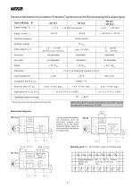
Electronic Modules for the excitation of Inductive Transducers and for the processing of the output signal Type of Module Oscillator frequency depending on type of transducer Ripple Attenuation Operating temperature range * Wiring instructions will be supplied with each item. Series OA and DE-modules as well as Multi-channel PC-boards are described in data sheet 10219AE Basic block diagrams RE Mounting grid 1:1 (5 mm pitch / view of mounting face) Case dimensions Solder pins Mass Current impressor The transmission line between the transducer and the electronic module may measure up to 100 meters....
Open the catalog to page 4All TWK-ELEKTRONIK GmbH catalogs and technical brochures
 Rotary encoder TBN58/C3 manual
50 Pages
 Rotary encoder TBN58/C3
22 Pages
 Rotary encoder TBD Manual
26 Pages
 Rotary encoder TBD
12 Pages
 Rotary encoder TBE58
16 Pages
 Rotary encoder KRP - Manual
19 Pages
 Rotary encoder KRP
7 Pages
 Rotary encoder TBN58/S4 SIL2
22 Pages
 Rotary encoder TBN50/C3 manual
20 Pages
 Rotary encoder TBN50/C3
22 Pages
 Rotary encoder HBN/S3 SIL2
16 Pages
 Product range 2022
64 Pages
 Image brochure TWK
28 Pages
 Inclinometer NBA51
6 Pages
 Incremental encoder FOI
7 Pages
 Rotary encoder TBA42
16 Pages
 Rotary encoder TRA42
16 Pages
 Rotary encoder TRN58/S4 SIL2
22 Pages
 Rotary encoder TRN58/C3 manual
50 Pages
 Rotary encoder TRN58/C3
22 Pages
 Rotary encoder TRN42/S4 SIL2
22 Pages
 Manual TRN50/C3
86 Pages
 Rotary encoder TRN50/C3
22 Pages
 Rotary encoder TRN42/C3 manual
86 Pages
 Rotary encoder TRN42/C3
22 Pages
 Rotary encoder TBN42/S4 SIL2
22 Pages
 Rotary encoder TBN42/C3 manual
86 Pages
 Rotary encoder TBN42/C3
22 Pages
 Rotary encoder TRE58
16 Pages
 Rotary encoder TRT manual
40 Pages
 Rotary encoder TRT
14 Pages
 Switching cam encoder NOCE
14 Pages
 Switching cam encoder NOCA
17 Pages
 Vibration sensor NVT/S3 PLd
12 Pages
 Vibration sensor NVA
12 Pages
 Inclinometer NBN
17 Pages
 Incremental encoder TBI42
6 Pages
 Vibration sensor NVA/S3 PLd
15 Pages
 Rotary transducer PMR411
1 Page
 Rotary encoder TRT/S3 SIL2
13 Pages
 Rotary transducer VP12
1 Page
 Switching cam encoder NOCN
22 Pages
 Inclination sensor NBT manual
21 Pages
 Inclination sensor NBT
10 Pages
 Inclinometer NBA
17 Pages
 Inclinometer NBT/S3 SIL2/PLd
12 Pages
 Inclinometer NBN/S3 SIL2
13 Pages
 Rotary encoder TBE50
16 Pages
 Rotary encoder HBE
14 Pages
 Rotary encoder TRK manual
18 Pages
 Rotary encoder TRK
11 Pages
 Rotary encoder TMN50 manual
22 Pages
 Rotary encoder TMN50
6 Pages
 Rotary encoder TRK/S3 SIL2
14 Pages
 Rotary encoder TRE42
6 Pages
 Rotary encoder TRE50
6 Pages
 Rotary encoder TRA50
6 Pages
 Rotary encoder TBE42
6 Pages
 Rotary encoder TME42
6 Pages
 Rotary encoder TRD manual
26 Pages
 Rotary encoder TRD
12 Pages
 Rotary encoder TME50
6 Pages
 Rotary encoder TBN36
6 Pages
 Rotary encoder TMA50
6 Pages
 Rotary encoder TMN42 manual
22 Pages
 Rotary encoder TMN42
6 Pages
 Rotary encoder TMA42
6 Pages
 Rotary encoder TBA50
16 Pages
 Rotary encoder TBE36 manual
22 Pages
 Rotary encoder TBE36
6 Pages
 Rotary encoder TBN42
6 Pages
 Rotary encoder TBN37
8 Pages
 Rotary encoder TBA37
7 Pages
 Rotary encoder TBB50
16 Pages
 Rotary encoder PBA12
2 Pages
 Rotary encoder TBA36
6 Pages
 Rotary encoder TKA60
2 Pages
 Rotary encoder TKN46 manual
22 Pages
 Rotary encoder TKN46
7 Pages


- SARRALLE rotary encoder
- SARRALLE incremental encoder
- SARRALLE incremental rotary encoder
- SARRALLE absolute rotary encoder
- SARRALLE inclinometer
- SARRALLE magnetic rotary encoder
- Industrial rotary encoder
- Displacement transducer
- Linear displacement sensor
- SARRALLE digital inclinometer
- SARRALLE aluminum rotary encoder
- SARRALLE stainless steel rotary encoder
- SARRALLE single-turn rotary encoder
- MEMS inclination sensor
- Flange rotary encoder
- Multi-axis tilt sensor
- SARRALLE ultra-rugged rotary encoder
- SSI angular encoder
- SARRALLE multi-turn rotary encoder
- Analog displacement transducer