- Catalogs
- TWK-ELEKTRONIK GmbH
- Inductive displacement transducers IWN250 manual
- Company
- Products
- Catalogs
- News & Trends
- Exhibitions
Inductive displacement transducers IWN250 manual
1 /20Pages

Inductive displacement transducers IWN250 manual
1 /20Pages
Catalog excerpts

Inductive Linear Displacement Transducers with CANopen Interface CANopen User Manual IE25, IWN TWK-ELEKTRONIK GmbH · PB. 10 50 63 · D-40041 Düsseldorf
Open the catalog to page 1
COPYRIGHT: The IWN 11307 operating instructions are owned by TWK-ELEKTRONIK GMBH and are protected by copyright laws and international treaty provisions. © 2010 by TWK-ELEKTRONIK GMBH POB 10 50 63 ■ 40041 Dusseldorf ■ Germany Tel. +49/211 /63 20 67 ■ Fax +49/211 /63 77 05 [email protected] ■ www.twk.de
Open the catalog to page 2
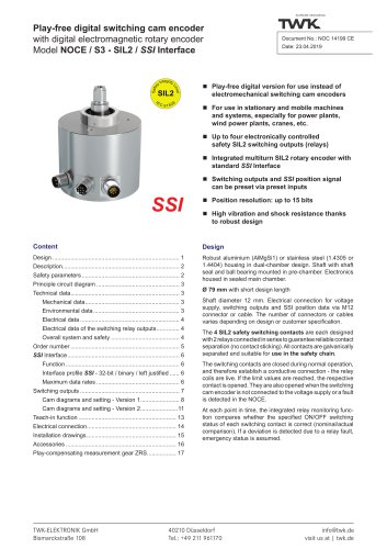
1.1 Scope of validity This user manual applies exclusively to the following rotary encoders with PROFIsafe interface: - IWN - IE25 1.2 Documentation The following documents must be noted: - The owner's system-specific operating instructions - This user manual - For IWN: Data sheet number 11253 IE25: Data sheet number 11253 and 11359 as well as the data sheet of the used linear transducer 1.3 Proper use TWK-ELEKTRONIK GmbH's rotary encoders and linear transducers are used to record rotary and linear positions, and make their measured values available as an electric output signal. As part of a...
Open the catalog to page 5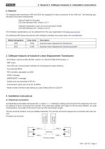
2. General The displacement transducers IWN and IE25 are designed for direct connection to the CAN bus. The following specifications have been implemented: Device Profile for Encoders CiA Draft Standard 406, Version 3.0 /1/ CANopen Application Layer and Communication Profile CiA Draft Standard 301, Version 4.02 /2/ The CANopen specifications can be obtained from the user organisation CiA (www.can-cia.org). The following IWN Series transducers with CANopen interface have been taken into consideration: * Terminal resistor
Open the catalog to page 6
4.2 Baud rates and lead lengths Note: The transducers has no galvanic separation between the supply voltage and bus leads; the total bus length is therefore limited to 200 m. 4.3 Setting the address and Baud rate The node address (node number) and the Baud rate are set via the LSS - Layer Setting Service (see CiA DS 305). In this case, each node has a unique LSS address, via which it can be identified in the network. This is comprised of the following: Manufacturer ID: 0000 010Dh (TWK manufacturer ID) Product number: 0000 5000h (TWK product number) Revision number: 0001 0001h (current revision...
Open the catalog to page 7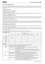
5. Process data exchange 5. Process data exchange In the case of CANopen, I/O data traffic takes place via the PDO (Process Data Object) message. The IWN and IE25 Series transducers provide two PDOs. Their transmission behaviour (transmission type) can be set independently of each other. The following operating modes can be set: PoNing Mode (asynchronous-RTR): The transducer transmits the current, actual position value, after the current position value has been polled via a „Re-mote Frame“ message by the master. Asynchronous Mode (cyclic / acyclic): Without being requested to do so by the master,...
Open the catalog to page 8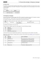
5.2 Data format The definition of the output data (mapping) and their depiction is identical for both PDOs. The position value is output in steps (Index 6004h) as 12 bit value. The resolution in nm/step depends on the measuring range and can be read unter index 6501 h Position value
Open the catalog to page 9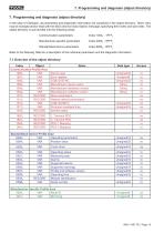
7. Programming and diagnosis (object directory) 7. Programming and diagnosis (object directory) In the case of CANopen, all parameters and diagnostic information are contained in the object directory. There, they may be changed and/or read with the SDO (Service Data Object) message, specifying their index and sub-index. The object directory is sub-divided into the following areas: Communication parameters Index 1000h - 1FFFh Manufacturer-specific parameters Index 2000h - 5FFFh Standardised device parameters Index 6000h - 9FFFh Refer to the following Table for a description of the individual parameters...
Open the catalog to page 10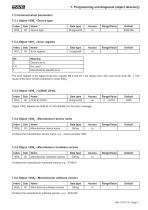
7.2 Communication parameters 7.2.1 Object 1000h - Device type Contains the manufacturer software version, e.g.: „IWN Std“
Open the catalog to page 11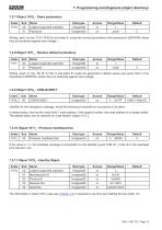
7. Programming and diagnosis (object directory) 7.2.7 Object 1010h - Store parameters The information in object 1018h (also see Chapter 4.3) is required to use the Layer Setting Service (LSS, /4/).
Open the catalog to page 12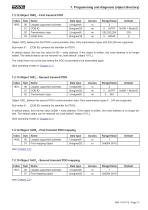
7.2.12 Object 1800h - First transmit PDO
Open the catalog to page 13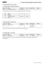
7. Programming and diagnosis (object directory) 7.3 Standardised device parameters 7.3.1 Object 6000h - Operating parameters In the case of values of > 0 ms for the cyclic timer, the position value is transmitted cyclically with PDO 1 (see Chapter 5).
Open the catalog to page 14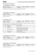
7.4 Standardised device diagnosis 7.4.1 Object 6500h - Operating status
Open the catalog to page 15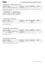
7. Programming and diagnosis (object directory) 7.4.6 Object 6507h - Profile and software version The object contains the device‘s serial number.
Open the catalog to page 16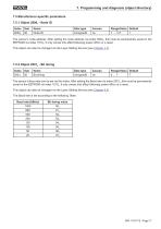
7.5 Manufacturer-specific parameters 7.5.1 Object 2000h - Node ID
Open the catalog to page 17
8. Examples Message traffic between a master and the sensor IWN during boot-up, when changing a parameter and when setting the slave address with LSS is shown in the following. The identifier (ID), the transmission direction (Rx/Tx), the Data Length Code (DLC) and the data bytes are shown in tabular form. The following applies: - The sensor has the address 1 (default) and is the only slave - Sensor with default parameter values - Tx: Master transmits data to the sensor - Rx: Sensor transmits data 8.1 Boot-up The following Table shows the sensor boot-up, from switching on the supply voltage to...
Open the catalog to page 18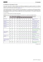
8.3 Setting the node address via LSS In the case of the LSS /4/, either all CANopen subscribers are addressed via a global command or an individual subscriber is addressed via its LSS address, which is comprised of the manufacturer name, the product name, the revision number and the serial number (see Chapter 4.3). In the following example, the sensor is addressed via its LSS address (i.e. is switched from LSS-Operation-Mode to LSS-Configuration-Mode), node address 2 is programmed and saved. LSS-Operation-Mode is subsequently reset. The sensor then reboots and logs on (without voltage off/on)...
Open the catalog to page 19
/1/ CiA Draft Standard 406, Version 3.0, Device Profile for Encoders 121 CiA Draft Standard 301, Version 4.02, CANopen Application Layer and Communication Profile /3/ CiA Draft Recommendation Proposal 303-1, Version 1.1.1 CANopen Cabling and Connector Pin Assignment /4/ CiA Draft Standard Proposal 305, Version 1.1.1, CANopen Layer Setting Services and Protocol (LSS)
Open the catalog to page 20All TWK-ELEKTRONIK GmbH catalogs and technical brochures
 Rotary encoder TBN58/C3 manual
50 Pages
 Rotary encoder TBN58/C3
22 Pages
 Rotary encoder TBD Manual
26 Pages
 Rotary encoder TBD
12 Pages
 Rotary encoder TBE58
16 Pages
 Rotary encoder KRP - Manual
19 Pages
 Rotary encoder KRP
7 Pages
 Rotary encoder TBN58/S4 SIL2
22 Pages
 Rotary encoder TBN50/C3 manual
20 Pages
 Rotary encoder TBN50/C3
22 Pages
 Rotary encoder HBN/S3 SIL2
16 Pages
 Product range 2022
64 Pages
 Image brochure TWK
28 Pages
 Inclinometer NBA51
6 Pages
 Incremental encoder FOI
7 Pages
 Rotary encoder TBA42
16 Pages
 Rotary encoder TRA42
16 Pages
 Rotary encoder TRN58/S4 SIL2
22 Pages
 Rotary encoder TRN58/C3 manual
50 Pages
 Rotary encoder TRN58/C3
22 Pages
 Rotary encoder TRN42/S4 SIL2
22 Pages
 Manual TRN50/C3
86 Pages
 Rotary encoder TRN50/C3
22 Pages
 Rotary encoder TRN42/C3 manual
86 Pages
 Rotary encoder TRN42/C3
22 Pages
 Rotary encoder TBN42/S4 SIL2
22 Pages
 Rotary encoder TBN42/C3 manual
86 Pages
 Rotary encoder TBN42/C3
22 Pages
 Rotary encoder TRE58
16 Pages
 Rotary encoder TRT manual
40 Pages
 Rotary encoder TRT
14 Pages
 Switching cam encoder NOCE
14 Pages
 Switching cam encoder NOCA
17 Pages
 Vibration sensor NVT/S3 PLd
12 Pages
 Vibration sensor NVA
12 Pages
 Inclinometer NBN
17 Pages
 Incremental encoder TBI42
6 Pages
 Vibration sensor NVA/S3 PLd
15 Pages
 Rotary transducer PMR411
1 Page
 Rotary encoder TRT/S3 SIL2
13 Pages
 Rotary transducer VP12
1 Page
 Switching cam encoder NOCN
22 Pages
 Inclination sensor NBT manual
21 Pages
 Inclination sensor NBT
10 Pages
 Inclinometer NBA
17 Pages
 Inclinometer NBT/S3 SIL2/PLd
12 Pages
 Inclinometer NBN/S3 SIL2
13 Pages
 Rotary encoder TBE50
16 Pages
 Rotary encoder HBE
14 Pages
 Rotary encoder TRK manual
18 Pages
 Rotary encoder TRK
11 Pages
 Rotary encoder TMN50 manual
22 Pages
 Rotary encoder TMN50
6 Pages
 Rotary encoder TRK/S3 SIL2
14 Pages
 Rotary encoder TRE42
6 Pages
 Rotary encoder TRE50
6 Pages
 Rotary encoder TRA50
6 Pages
 Rotary encoder TBE42
6 Pages
 Rotary encoder TME42
6 Pages
 Rotary encoder TRD manual
26 Pages
 Rotary encoder TRD
12 Pages
 Rotary encoder TME50
6 Pages
 Rotary encoder TBN36
6 Pages
 Rotary encoder TMA50
6 Pages
 Rotary encoder TMN42 manual
22 Pages
 Rotary encoder TMN42
6 Pages
 Rotary encoder TMA42
6 Pages
 Rotary encoder TBA50
16 Pages
 Rotary encoder TBE36 manual
22 Pages
 Rotary encoder TBE36
6 Pages
 Rotary encoder TBN42
6 Pages
 Rotary encoder TBN37
8 Pages
 Rotary encoder TBA37
7 Pages
 Rotary encoder TBB50
16 Pages
 Rotary encoder PBA12
2 Pages
 Rotary encoder TBA36
6 Pages
 Rotary encoder TKA60
2 Pages
 Rotary encoder TKN46 manual
22 Pages
 Rotary encoder TKN46
7 Pages


- SARRALLE incremental encoder
- SARRALLE incremental rotary encoder
- SARRALLE absolute rotary encoder
- SARRALLE inclinometer
- SARRALLE magnetic rotary encoder
- Industrial rotary encoder
- Displacement transducer
- Linear displacement sensor
- SARRALLE digital inclinometer
- SARRALLE aluminum rotary encoder
- SARRALLE stainless steel rotary encoder
- SARRALLE single-turn rotary encoder
- MEMS inclination sensor
- Flange rotary encoder
- Multi-axis tilt sensor
- SARRALLE ultra-rugged rotary encoder
- SSI angular encoder
- SARRALLE multi-turn rotary encoder
- Analog displacement transducer