Catalog excerpts

Inductive Linear Displacement Transducers Model IWE 260 Measuring strokes : 80 mm, 170 mm, 240 mm, 360 mm ■ Contactless, robust sensor system ■ Infinite resolution, no hysteresis ■ Digital interface SSI ■ Resolution 12 Bits / natural binary ■ Gauge with spring return up to 100 mm ■ Protection class IP 66 Construction and operating principle The displacement transducer operates according to the principle of the differential choke, i.e. an inductive half bridge. It consists of two coils which are encapsulated in a stainless steel cylinder. A mu-metal plunger core causes opposing changes of inductance when it is displaced through the centre of the coils. These changes are converted by the integral electronic circuit into a signal proportional to the displacement. A 12 bits A/D converter supplied a proportional digital signal wich can be calibrated before delivery via on integral-controler. The transducers are completely sealed to ensure positive protection against vibration, shock, humidity, oil and corrosive matter. Standard measuring strokes: 80 mm, 170 mm, 240 mm, 360 mm Special calibration Up on request the measuring stroke can be reduced without affecting neither the resolution nor the case length, e.g. 200 mm measuring stroke (IWE 260/200) will be generated using IWE 260/40. Electrical data ■ Supply voltage range VS : 21.5 to 30 VDC (prot'd against reverse polarity) ■ Output code: ■ Data output: ■ Clock input: ■ Monoflops rate: ■ Clock frequency: ■ Interface profile: ■ Linearity: ■ Temperature drift: ■ Stability: ■ Measurement frequency: Natural binary SS/-Differential SS/-Differential to RS 422 10 to 30 ps 125 kHz SSI 13 Bits 0.5 % or 0.25 % < 0.01 %/°C < 0.1 % in 24 hours 100 Hz max. Note: If not otherwise indicated all data are valid at 20° C ambiant temperature, at Vs = 24 VDC and 30 min. turn-on time. Measuring direction The measuring signal increases when the plunger moves in direction of the connector. Up to request the reverse action can be calibrated before delivery. TWK-ELEKTRONIK GmbH BismarckstraBe 108 Environmental data ■ Operating temperature range: ■ Storage temperature range: ■ Resistance to shock: ■ Resistance to vibration: ■ Protection class: Materials □ External and internal tube □ Plunger : □ Core : □ Connector case : □ Connector contacts : □ Spring and gauge head : Chrome-nickel steel Chrome-nickel steel Mu-metal Brass, nickel-plated Gold-plated Stainless steel ("T")
Open the catalog to page 1
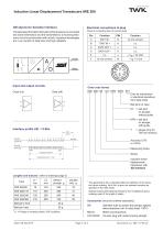
Inductive Linear Displacement Transducers IWE 260 SSI (Synchron Serielles Interface) The absolute information derived by the transducer is converted into serial information and the transmitted to a receiving electronic circuit in synchronism with aclock. Important advantages are: Low number of data lines and high reliability. Electrical connections at plug (View at connecting face of counter plug) L1 = Plunger in central position: 2047 positions. The applicable A-No. is allocated after the definition of the deviation when ordering. No A-No. is given for standard versions as specified in the...
Open the catalog to page 2
Inductive Linear Displacement Transducers IWE 260 Dimensions in mm Stainless steel tube 1,4301 Standard version (without rod guide) Version with ball joint on plunger (KV) (without rod guide) pivot angle 13˚ Ø ø5H7 5 ø18 Ball joint head to DIN 648 Version with ball joints on plunger (KFN) and on end of case (KFH) (with rod guide, captivated) O 5 H7 Brass guide sleeve L1 +20 ±2 Version with cable output and cable gland MB 25 Mounting block, brass Nickel plated (to be ordered separately) Cable output lenght accoding to customer request. BM = Plunger in central position B1 = Plunger full out...
Open the catalog to page 3All TWK-ELEKTRONIK GmbH catalogs and technical brochures
-
Rotary encoder TBN58/C3 manual
50 Pages
-
Rotary encoder TBN58/C3
22 Pages
-
Rotary encoder TBD Manual
26 Pages
-
Rotary encoder TBD
12 Pages
-
Rotary encoder TBE58
16 Pages
-
Rotary encoder KRP - Manual
19 Pages
-
Rotary encoder KRP
7 Pages
-
Rotary encoder TBN58/S4 SIL2
22 Pages
-
Rotary encoder TBN50/C3 manual
20 Pages
-
Rotary encoder TBN50/C3
22 Pages
-
Rotary encoder HBN/S3 SIL2
16 Pages
-
Product range 2022
64 Pages
-
Image brochure TWK
28 Pages
-
Inclinometer NBA51
6 Pages
-
Incremental encoder FOI
7 Pages
-
Rotary encoder TBA42
16 Pages
-
Rotary encoder TRA42
16 Pages
-
Rotary encoder TRN58/S4 SIL2
22 Pages
-
Rotary encoder TRN58/C3 manual
50 Pages
-
Rotary encoder TRN58/C3
22 Pages
-
Rotary encoder TRN42/S4 SIL2
22 Pages
-
Manual TRN50/C3
86 Pages
-
Rotary encoder TRN50/C3
22 Pages
-
Rotary encoder TRN42/C3 manual
86 Pages
-
Rotary encoder TRN42/C3
22 Pages
-
Rotary encoder TBN42/S4 SIL2
22 Pages
-
Rotary encoder TBN42/C3 manual
86 Pages
-
Rotary encoder TBN42/C3
22 Pages
-
Rotary encoder TRE58
16 Pages
-
Rotary encoder TRT manual
40 Pages
-
Rotary encoder TRT
14 Pages
-
Switching cam encoder NOCE
14 Pages
-
Switching cam encoder NOCA
17 Pages
-
Vibration sensor NVT/S3 PLd
12 Pages
-
Vibration sensor NVA
12 Pages
-
Inclinometer NBN
17 Pages
-
Incremental encoder TBI42
6 Pages
-
Vibration sensor NVA/S3 PLd
15 Pages
-
Rotary transducer PMR411
1 Pages
-
Rotary encoder TRT/S3 SIL2
13 Pages
-
Rotary transducer VP12
1 Pages
-
Switching cam encoder NOCN
22 Pages
-
Inclination sensor NBT manual
21 Pages
-
Inclination sensor NBT
10 Pages
-
Inclinometer NBA
17 Pages
-
Inclinometer NBT/S3 SIL2/PLd
12 Pages
-
Inclinometer NBN/S3 SIL2
13 Pages
-
Rotary encoder TBE50
16 Pages
-
Rotary encoder HBE
14 Pages
-
Rotary encoder TRK manual
18 Pages
-
Rotary encoder TRK
11 Pages
-
Rotary encoder TMN50 manual
22 Pages
-
Rotary encoder TMN50
6 Pages
-
Rotary encoder TRK/S3 SIL2
14 Pages
-
Rotary encoder TRE42
6 Pages
-
Rotary encoder TRE50
6 Pages
-
Rotary encoder TRA50
6 Pages
-
Rotary encoder TBE42
6 Pages
-
Rotary encoder TME42
6 Pages
-
Rotary encoder TRD manual
26 Pages
-
Rotary encoder TRD
12 Pages
-
Rotary encoder TME50
6 Pages
-
Rotary encoder TBN36
6 Pages
-
Rotary encoder TMA50
6 Pages
-
Rotary encoder TMN42 manual
22 Pages
-
Rotary encoder TMN42
6 Pages
-
Rotary encoder TMA42
6 Pages
-
Rotary encoder TBA50
16 Pages
-
Rotary encoder TBE36 manual
22 Pages
-
Rotary encoder TBE36
6 Pages
-
Rotary encoder TBN42
6 Pages
-
Rotary encoder TBN37
8 Pages
-
Rotary encoder TBA37
7 Pages
-
Rotary encoder TBB50
16 Pages
-
Rotary encoder PBA12
2 Pages
-
Rotary encoder TBA36
6 Pages
-
Rotary encoder TKA60
2 Pages
-
Rotary encoder TKN46 manual
22 Pages
-
Rotary encoder TKN46
7 Pages


