- Catalogs
- TWK-ELEKTRONIK GmbH
- Inductive displacement transducer IWE260 system description
- Company
- Products
- Catalogs
- News & Trends
- Exhibitions
Inductive displacement transducer IWE260 system description
1 /8Pages

Inductive displacement transducer IWE260 system description
1 /8Pages
Catalog excerpts

Synchronous-Serial Interface for absolute Encoders TWK-ELEKTRONIK GmbH · D-40041 Düsseldorf · PB 105063 · Heinrichstr. 85 · Tel +49/211/632067 · Fax +49/211/637705 · e-mail: info@tw
Open the catalog to page 1
Advantage of the SSI over parallel interfaces Significantly less expenditure for cabling: In the case of 24 bit encoders, only 4 lines are needed for the transmission of data instead of 24. Expenditure for cabling and interface components does not depend on the length of the data word. Screening out of noise is achieved through the clock and data signals being transmitted synchronously and symmetrically via twisted pair lines. Multiple transmission of each data word provides an automatic plausibility check. Absolute Encoder and reception electronics are separated with opto-couplers rendering...
Open the catalog to page 3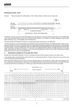
Example: Absolute Encoder with 4096 positions / 360°, 4096 revolutions and Gray tree as output code Idle state
Open the catalog to page 4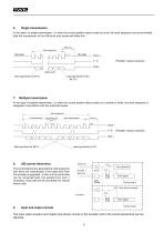
Single transmission In the case of a single transmission, i.e. when the current position data is read out once, the clock sequence can be terminated after the transmission of the LSB since only zeroes will follow this. Wait time Clock sequence Idle state Idle state (Parallel / serial converter) P/S Data + Data word Least significant bit (S1) Bit (S 1) Multiple transmission In the case of multiple transmission, i.e. when the current position data is read out a number of times, the clock sequence is designed in accordance with the schematic below. Clock sequence 1st transmission Intermediate clock...
Open the catalog to page 5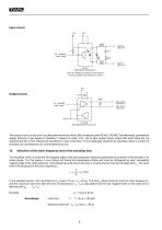
TTL / HCMOS Logik / Logic 91R 100R Takt IN-/ Clock IN6N137 (Optokoppler/Optocoupler ) LED z.B. LR3360 (rot) Siemens oder ähnliche LED e.g. LR3360 (red) Siemens or similar Output circuit 47nF 100pF Data OUT+/ Data OUT+ Data OUT-/ Data OUT- TTL / HCMOS Logik / Logic The output circuit is in the form of a differential line driver which fulfils complaying with RS 422 / RS 485. The differential, symmetrical design ensures a high degree of reliability in respect of noise. The use of opto-coupler inputs means that earth loops are not required and this in turn reduces the sensitivity to noise still further....
Open the catalog to page 6
Maximum data transmission rate [MHz] maximum Baud rate in acc. with RS 422 The maximum achievable data transmission rate (clock frequency) is set for the drivers and reception electronics used as well as for the transmission protocol in accordance with the RS 422 standard. It must be one half of the values stated in the standard for the Baud rate. Both limit curves are shown in the adjoining graph. It is shown below how the maximum data transmission rate can be achieved by means of measures on the reception electronics side by taking into account the different transit times. maximum clock frequency...
Open the catalog to page 7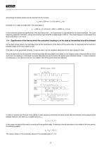
Accordingly the above values can be inserted into the formula tTD (ns) = 300 ns + 2 x 6.5 ns/m x lCA (m) Example: For a cable of length 200 m the total delay is tTD = 300 ns + 2 x 6.5 ns/m x 200 m = 2900 ns = 2.9 µs In the schematic below the significance of the total delay time t for transmission is represented for the above example. The clock TD frequency selected is 300 kHz, namely the maximum permitted for a cable length of 200 m. This clock frequency is equivalent to a clock cycle time (tT) of 3.3 µs. 11.4 Significance of the time by which the evaluation (reading-in) of the data as transmitted...
Open the catalog to page 8All TWK-ELEKTRONIK GmbH catalogs and technical brochures
 Rotary encoder TBN58/C3 manual
50 Pages
 Rotary encoder TBN58/C3
22 Pages
 Rotary encoder TBD Manual
26 Pages
 Rotary encoder TBD
12 Pages
 Rotary encoder TBE58
16 Pages
 Rotary encoder KRP - Manual
19 Pages
 Rotary encoder KRP
7 Pages
 Rotary encoder TBN58/S4 SIL2
22 Pages
 Rotary encoder TBN50/C3 manual
20 Pages
 Rotary encoder TBN50/C3
22 Pages
 Rotary encoder HBN/S3 SIL2
16 Pages
 Product range 2022
64 Pages
 Image brochure TWK
28 Pages
 Inclinometer NBA51
6 Pages
 Incremental encoder FOI
7 Pages
 Rotary encoder TBA42
16 Pages
 Rotary encoder TRA42
16 Pages
 Rotary encoder TRN58/S4 SIL2
22 Pages
 Rotary encoder TRN58/C3 manual
50 Pages
 Rotary encoder TRN58/C3
22 Pages
 Rotary encoder TRN42/S4 SIL2
22 Pages
 Manual TRN50/C3
86 Pages
 Rotary encoder TRN50/C3
22 Pages
 Rotary encoder TRN42/C3 manual
86 Pages
 Rotary encoder TRN42/C3
22 Pages
 Rotary encoder TBN42/S4 SIL2
22 Pages
 Rotary encoder TBN42/C3 manual
86 Pages
 Rotary encoder TBN42/C3
22 Pages
 Rotary encoder TRE58
16 Pages
 Rotary encoder TRT manual
40 Pages
 Rotary encoder TRT
14 Pages
 Switching cam encoder NOCE
14 Pages
 Switching cam encoder NOCA
17 Pages
 Vibration sensor NVT/S3 PLd
12 Pages
 Vibration sensor NVA
12 Pages
 Inclinometer NBN
17 Pages
 Incremental encoder TBI42
6 Pages
 Vibration sensor NVA/S3 PLd
15 Pages
 Rotary transducer PMR411
1 Page
 Rotary encoder TRT/S3 SIL2
13 Pages
 Rotary transducer VP12
1 Page
 Switching cam encoder NOCN
22 Pages
 Inclination sensor NBT manual
21 Pages
 Inclination sensor NBT
10 Pages
 Inclinometer NBA
17 Pages
 Inclinometer NBT/S3 SIL2/PLd
12 Pages
 Inclinometer NBN/S3 SIL2
13 Pages
 Rotary encoder TBE50
16 Pages
 Rotary encoder HBE
14 Pages
 Rotary encoder TRK manual
18 Pages
 Rotary encoder TRK
11 Pages
 Rotary encoder TMN50 manual
22 Pages
 Rotary encoder TMN50
6 Pages
 Rotary encoder TRK/S3 SIL2
14 Pages
 Rotary encoder TRE42
6 Pages
 Rotary encoder TRE50
6 Pages
 Rotary encoder TRA50
6 Pages
 Rotary encoder TBE42
6 Pages
 Rotary encoder TME42
6 Pages
 Rotary encoder TRD manual
26 Pages
 Rotary encoder TRD
12 Pages
 Rotary encoder TME50
6 Pages
 Rotary encoder TBN36
6 Pages
 Rotary encoder TMA50
6 Pages
 Rotary encoder TMN42 manual
22 Pages
 Rotary encoder TMN42
6 Pages
 Rotary encoder TMA42
6 Pages
 Rotary encoder TBA50
16 Pages
 Rotary encoder TBE36 manual
22 Pages
 Rotary encoder TBE36
6 Pages
 Rotary encoder TBN42
6 Pages
 Rotary encoder TBN37
8 Pages
 Rotary encoder TBA37
7 Pages
 Rotary encoder TBB50
16 Pages
 Rotary encoder PBA12
2 Pages
 Rotary encoder TBA36
6 Pages
 Rotary encoder TKA60
2 Pages
 Rotary encoder TKN46 manual
22 Pages
 Rotary encoder TKN46
7 Pages


- Angular encoder
- Incremental encoder
- Incremental rotary encoder
- Absolute rotary encoder
- Tilt sensor
- Magnetic rotary encoder
- Industrial rotary encoder
- Displacement transducer
- Linear displacement sensor
- Digital inclination sensor
- Aluminum rotary encoder
- Stainless steel rotary encoder
- Single-turn rotary encoder
- MEMS inclination sensor
- Flange rotary encoder
- Multi-axis tilt sensor
- Ultra-rugged rotary encoder
- SSI angular encoder
- Multi-turn rotary encoder
- Analog displacement transducer