
- Catalogs
- TWK-ELEKTRONIK GmbH
- Inclinometer NBT/S3 SIL2/PLd

Inclinometer NBT/S3 SIL2/PLd

Inclinometer NBT/S3 SIL2/PLd
- Measurement Axes: 1 or 2
- Measuring Range: Selectable from ±5° to ±90°
- Housing Material: Aluminium or stainless steel
- Protection Type: Up to IP69K
- Certification: TÜV certified as of hardware version 2
- Accuracy: ±0.25° to ±0.5° depending on the measuring angle and conditions
- Drift: Varies with temperature, from ±0.3° to ±0.6°
- Response Time: 1 second for full value change
- Operating Temperature: -40°C to +70°C
- Shock and Vibration Resistance: Compliant with DIN EN standards
- Power Supply: 9 to 36 VDC, <3 W power consumption
Catalog excerpts

FUNCTIONAL SAFETY SENSOR ■ SIL2 and Performance Level d ■ Number of measurement axes: 1 or 2 ■ Selectable measuring range: ± 5° to ± 90° ■ With preset function ■ Housing: aluminium or stainless steel ■ Protection type: up to IP69K ■ As of hardware version 2 TUV certified Design and function The inclinometer measures the inclination in the gravitational field by means of MEMS sensors (Micro-Electro-Mechanical-System) with subsequent digitisation and linearisation via controllers. It has a stable aluminium housing (optionally stainless steel) and is highly-resistant to vibration and shock. Casting measures in the housing lead to the achievement of protection class IP 69K. MEMS sensors are integrated circuits manufactured using silicon bulk micromechanical technology. Double capacities are formed with the aid of moveable micromechanical structures. If these structures are deflected in the case of acceleration, e.g. gravitational acceleration (g), this results in capacity changes, which are registered and further processed using measuring technology. The output voltage follows the function U ~ g * sin a. In this case, the angle a is the sensor's inclination angle measured against the g vector. These sensors measure precisely, have a long service life and are very robust. The measuring axes operate independently of each other. The NBT has a redundant MEMS sensor system, which is used to make a plausibility check inside the inclinometer. Only one position datum is output; the plausibility of this is checked using the second system's position datum. Is the deviation of the two systems higher than a certain value, the sensor will enter the failsafe state. The Profinet interface according to IEC 61158 / 61784 or PNO specifications order No. 2.712 and 2.722, version 2.3, is integrated into the inclinometer series NBT/S3. Real time classes 1 and 3 are supported, i.e. Real Time (RT) and Isochronous Real Time (IRT) plus the requirements of conformance class C.The integrated 2-fold switch enables the TWK PROFINET inclinometer to be used in star, tree and line network topologies. The PROFIsafe protocol is implemented according to the PROFIisafe Profile for Safety Technologie version 2.4 (PNO Order No. 3.192). An exhaustive description of integration into a PROFINET network can be found in the NBT13912 manual. PROFINET properties - Real Time (RT) and Isochronous Real Time (IRT) - Device exchange without interchangeable medium or programming device - Prioritised start-up (Fast Start Up) - Media redundancy possible - Firmware update via Profinet TWK-ELEKTRONIK GmbH BismarckstraBe 108 [email protected] visit us at | twk.de
Open the catalog to page 1
SUPREME SENSORING General description Behaviour in the event of a measured value change due to averaging: Dynamic, arithmetic averaging of the measured values is implemented in the inclinometer. This involves linear averaging over 1000 values, whereby a new value is recorded every millisecond. This results in a low-pass effect. In the event of an abrupt change in the measuring angle, the end value is reached after approx. 1 second. In the event of a linear change in the measuring angle, the relevant output signal follows after a delay of approx. 0.6 seconds. Other, e.g. shorter, values may be...
Open the catalog to page 2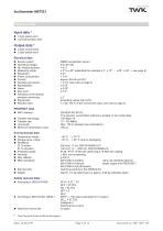
SUPREME SENSORING Technical data Input data * ■ 2 byte status word ■ 3x2 byte position data Output data * ■ 2 byte control word ■ 2 byte preset word Electrical data ■ Sensor system: ■ Operating voltage: ■ No. measuring axes: ■ Measuring range: ■ Resolution: ■ Power consumption: ■ Current: ■ Absolute accuracies: ■ Repeatability: ■ Noise: ■ Zero error: ■ Tolerance of the internal deviation monitoring: ■ Signal path: ■ Reaction time: PROFINET data ■ MAC address: ■ Transfer technology ■ Transfer rate ■ Line length ■ Minimum transmission cycle Environmental data ■ Temperature range:: ■ Storage temp....
Open the catalog to page 3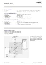
Inclinometer NBT/S3 Technical data Electrical connection PROFINET: Supply: M12 connector D-coded 4-pin for bus in / bus out, socket or cable output via cable glands M12 connector A-coded 4-pin, pins or cable output via cable glands Cable output PROFINET (optional) Cable type: Cable jacket: Temperatur range: Outer diameter: Min. bend radius: PROFINET Type-C, 4 x 0,36 mm2 (AWG22) PUR, color: green - 40 °C to + 70 °C 6.5 mm ± 0.2 mm 5 x d fixed installation, 10 x d freely movable Cable output power supply (optional) Cable type: Cable jacket: Temperatur range: Outer diameter:...
Open the catalog to page 4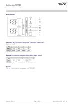
SUPREME SENSORING Electrical connectionBlock diagram PROFINET M12 connection assignment connector / cable output (Portl und Port 2) Supply M12 connection assignment connector / cable output PIN Remark Only use shielded cable for power supply and PROFINET. Date: 15.08.2019 Page 5 of 12 Document no. NBT 13911 HE
Open the catalog to page 5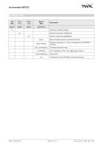
SUPREME SENSORING Date: 15.08.2019 Page 6 of 12 Document no. NBT 13911 HE
Open the catalog to page 6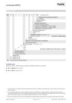
SUPREME SENSORING ^ Standardversion Electrical and mechanical variants Standard Output interface: T PROFINET Electrical connections: 1 Connector (hybrid connector) 2 Connector (1x PROFINET, 1x power supply) 3 Connector (2x PROFINET, 1x power supply) x Cable length in m (for cable output) S Connector M12 K Cable Installation position (See pages 11-12): 1 TOP 1, 2, 3, 4, 5, 6 See below: Available types S3 PROFIsafe, SIL2 Behaviour during disturbance acceleration: V Standard (See page 2) Measuring ranges 23 (See pages 11-12): ± z° z-axis ± y° y-axis ± x° x-axis See below: Available types. Other...
Open the catalog to page 7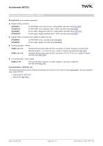
SUPREME SENSORING Accessories, documentation, GSD file Accessories (to be ordered separately) ■ Straight mating connector for PROFINET in/out (die-cast zinc, nickel-plated), see data sheet STK14570 for PROFINET in/out (stainless steel 1.4404), see data sheet STK14569 for the supply voltage (die-cast zinc, nickel-plated), see data sheet STK14572 for the supply voltage (stainless steel 1.4404), see data sheet STK14571 ■ Angled mating connector (only suitable for design form 90) STK4WP82 for PROFINET in/out, see data sheet STK14676 STK4WS61 for the supply voltage, see data sheet STK14675 ■ Connecting...
Open the catalog to page 8All TWK-ELEKTRONIK GmbH catalogs and technical brochures
 Rotary encoder TBN58/C3 manual
50 Pages
 Rotary encoder TBN58/C3
22 Pages
 Rotary encoder TBD Manual
26 Pages
 Rotary encoder TBD
12 Pages
 Rotary encoder TBE58
16 Pages
 Rotary encoder KRP - Manual
19 Pages
 Rotary encoder KRP
7 Pages
 Rotary encoder TBN58/S4 SIL2
22 Pages
 Rotary encoder TBN50/C3 manual
20 Pages
 Rotary encoder TBN50/C3
22 Pages
 Rotary encoder HBN/S3 SIL2
16 Pages
 Product range 2022
64 Pages
 Image brochure TWK
28 Pages
 Inclinometer NBA51
6 Pages
 Incremental encoder FOI
7 Pages
 Rotary encoder TBA42
16 Pages
 Rotary encoder TRA42
16 Pages
 Rotary encoder TRN58/S4 SIL2
22 Pages
 Rotary encoder TRN58/C3 manual
50 Pages
 Rotary encoder TRN58/C3
22 Pages
 Rotary encoder TRN42/S4 SIL2
22 Pages
 Manual TRN50/C3
86 Pages
 Rotary encoder TRN50/C3
22 Pages
 Rotary encoder TRN42/C3 manual
86 Pages
 Rotary encoder TRN42/C3
22 Pages
 Rotary encoder TBN42/S4 SIL2
22 Pages
 Rotary encoder TBN42/C3 manual
86 Pages
 Rotary encoder TBN42/C3
22 Pages
 Rotary encoder TRE58
16 Pages
 Rotary encoder TRT manual
40 Pages
 Rotary encoder TRT
14 Pages
 Switching cam encoder NOCE
14 Pages
 Switching cam encoder NOCA
17 Pages
 Vibration sensor NVT/S3 PLd
12 Pages
 Vibration sensor NVA
12 Pages
 Inclinometer NBN
17 Pages
 Incremental encoder TBI42
6 Pages
 Vibration sensor NVA/S3 PLd
15 Pages
 Rotary transducer PMR411
1 Page
 Rotary encoder TRT/S3 SIL2
13 Pages
 Rotary transducer VP12
1 Page
 Switching cam encoder NOCN
22 Pages
 Inclination sensor NBT manual
21 Pages
 Inclination sensor NBT
10 Pages
 Inclinometer NBA
17 Pages
 Inclinometer NBN/S3 SIL2
13 Pages
 Rotary encoder TBE50
16 Pages
 Rotary encoder HBE
14 Pages
 Rotary encoder TRK manual
18 Pages
 Rotary encoder TRK
11 Pages
 Rotary encoder TMN50 manual
22 Pages
 Rotary encoder TMN50
6 Pages
 Rotary encoder TRK/S3 SIL2
14 Pages
 Rotary encoder TRE42
6 Pages
 Rotary encoder TRE50
6 Pages
 Rotary encoder TRA50
6 Pages
 Rotary encoder TBE42
6 Pages
 Rotary encoder TME42
6 Pages
 Rotary encoder TRD manual
26 Pages
 Rotary encoder TRD
12 Pages
 Rotary encoder TME50
6 Pages
 Rotary encoder TBN36
6 Pages
 Rotary encoder TMA50
6 Pages
 Rotary encoder TMN42 manual
22 Pages
 Rotary encoder TMN42
6 Pages
 Rotary encoder TMA42
6 Pages
 Rotary encoder TBA50
16 Pages
 Rotary encoder TBE36 manual
22 Pages
 Rotary encoder TBE36
6 Pages
 Rotary encoder TBN42
6 Pages
 Rotary encoder TBN37
8 Pages
 Rotary encoder TBA37
7 Pages
 Rotary encoder TBB50
16 Pages
 Rotary encoder PBA12
2 Pages
 Rotary encoder TBA36
6 Pages
 Rotary encoder TKA60
2 Pages
 Rotary encoder TKN46 manual
22 Pages
 Rotary encoder TKN46
7 Pages




- Angular encoder
- Incremental encoder
- Incremental rotary encoder
- Absolute rotary encoder
- Industrial rotary encoder
- Magnetic rotary encoder
- Displacement transducer
- Linear displacement sensor
- Digital inclination sensor
- Aluminum rotary encoder
- Stainless steel rotary encoder
- Single-turn rotary encoder
- MEMS inclination sensor
- Flange rotary encoder
- Ultra-rugged rotary encoder
- Multi-axis tilt sensor
- SSI angular encoder
- Multi-turn rotary encoder
- Analog displacement transducer