- Catalogs
- TWK-ELEKTRONIK GmbH
- Inclinometer NBN/S3 SIL2
- Company
- Products
- Catalogs
- News & Trends
- Exhibitions
Inclinometer NBN/S3 SIL2
1 /13Pages

Inclinometer NBN/S3 SIL2
1 /13Pages
Catalog excerpts
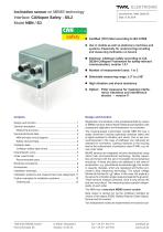
Inclination sensor on MEMS technology Interface: CANopen Safety - SIL2 Model NBN / S3 n Certified (TÜV) SIL2 according to IEC 61508 Use in mobile as well as stationary machines and systems. Especially for undercarriage levelling and measuring inclination on booms n Interface: CANopen safety according to CiA DS304 CANopen Framework for safety-relevant communication, version 1.0.1 n Number of measurement axes: 1 or 2 n Selectable measuring range: ± 5° to ± 90° n High vibration and shock resistance n Option: Filter measures for masking interfe- rence vibrations and interference shocks → version V Registration of inclination in the gravitational field by means of MEMS sensors (Micro-Electro-Mechanical-System) with subsequent digitisation and linearisation via controllers. The housing-based inclinometer (model NBN 65) has a stable aluminium housing (optionally stainless steel) and is highly-resistant to vibration and shock. One or two connectors/socket in the case of CANopen can optionally be selected for connection. Casting measures in the housing lead to the achievement of protection class IP 69K, e.g. for use under water. MEMS sensors are integrated circuits manufactured using silicon bulk micromechanical technology. Double capacities are formed with the aid of moveable micromechanical structures. If these structures are deflected in the case of acceleration, e.g. gravitational acceleration (g), this results in capacity changes, which are registered and further processed using measuring technology. The output voltage follows the function U ∝ g * sin α. In this case, the angle α is the sensor's inclination angle measured against the g vector. These sensors measure precisely, have a long service life and are very robust. The measuring axes operate independently of each other. The NBN has a redundant MEMS sensor system. Data output is carried out via the CANopen interface by means of the object SRDO (Safety Relevant Data Object). Normal and bit-inverted. Two independent nodes are implemented in the sensor sys- TWK-ELEKTRONIK GmbH Heinrichstrasse 85
Open the catalog to page 1
tem; in terms of logic, these behave as one node, i.e. both systems are addressed via one node address. The primary node controls the logical CANopen functions such as SDO processing, NMT and LSS services, and provides information to the redundant node via internal communication. The redundant node checks the safety parameters and internally compares its safety status with that of the primary node. A synchronisation check is carried out in the inclinometer. Only one position datum is output; the plausibility of this is checked using the second system's position datum. Is the deviation of the...
Open the catalog to page 2
Accuracy optional (not SIL 2 certified yet): Devices with 1 or 2 axes with a measuring angle of max. ±15° have an accuracy of ± 0.25°. This accuracy specification includes the following operating conditions: Lateral inclination up to and including ± 15°. An operating temperature range from -10°C to 60°C. (Measurement accuracy with lateral inclination of ~0° in a temperature range of +15°C to +30°C: 0.1°) Electrical data ■ Sensor system: ■ Operating voltage: ■ No. measuring axes: ■ Measuring range 1: ■ Resolution: ■ Power consumption: ■ Current: ■ Absolute accuracies: ■ Repeatability: ■ Noise:...
Open the catalog to page 3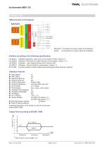
Inclinometer NBN / S3 CANopen data NBN principle circuit diagram Standard: 1 Connection for power supply and CANopen Option: 2 connections for power supply and CANopen Interface according to the following specifications CiA DS301 CiA DS304 CiA DS305 CiA DS410 IEC 61508 CANopen Application Layer and Communication Profile, Version 4.1 CANopen Framework for safety-relevant communication, Version 1.0.1 CANopen - Layer Setting Sevices and Protocol (LSS) CANopen - Device Profile for Inclinometers, Version 1.2 Functional safety of safety-related electrical/programmable electronic systems CANopen Features...
Open the catalog to page 4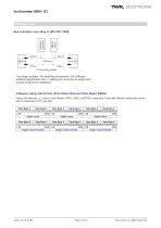
Bus activation according to ISO/ DIS 11898 The design guideline "CiA Draft Recommendation 303 CANopen additional specification Part 1: Cabling and connector pin assignment" must be observed on installation. CANopen safety data format, SIL2 (Safety Relevant Data Object SRDO) Output of three axis, x, y, and z, from Objects 6010h, 6020h und 6030h (maximum 2 axis with relevant measuring values, else 0). Resolution 0.01° per digit. Date: 21.03.2018 Page 5 of13 Document no. NBN12054 OE
Open the catalog to page 5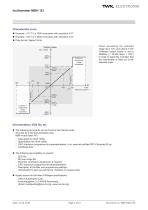
Inclinometer NBN / S3 Characteristic curve Characteristic curve ^ n Example: ± 70° = 2 x 7000 increments with resolution 0.01° ^ n Example: ± 20° = 2 x 2000 increments with resolution 0.01° n Data format: Signed 16-bit. Output value measuring range exceeded 1857 h 6999 When exceeding the selected range (eg ± 70°), plus about 2° the CANopen output values is set to 4650hex (= 18,000 steps = 180°) in order to signal the controller that the inclinometer is tilted out of the selected scale. measuring range exceeded Documentation, EDS file, etc. n The following documents can be found in the Internet...
Open the catalog to page 6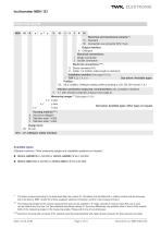
Inclinometer NBN / S3 Order code format NBN Electrical and mechanical variants *: Standard Connection via onnector M12, 5-pin c Output interface: N CANopen Electrical connections: 1 Single connection 2 Double connection Electrical connections ***: S Device connector M12 K Cable 1 m (further cable length on demand) Installation position (See pages 12-13): See below: Available types 1 TOP 1, 2, 3, 4, 5, 6 Profiles: S3 SIL2 certified. CANopen safety profile according to CiA, DS 304 version 1.0.1 V Vibration protection measures: recommended (only complete if desired): V = with vibration protection...
Open the catalog to page 7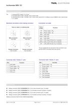
Inclinometer NBN / S3Electrical connections Via: - 1 connector M12 (male), 5- or 8-pin - 2 connectors M12 (male + female), 8-pin in each case - 2 connectors M12 (male + female), 5-pin in each case (Variant 50 in CANopen sensor NBN65 order code format) - 1 or 2 cables Electrical connection at the mating connector Connection via cable Colour of wire The pin assignment can be found in the connection assignment which is enclosed with each device. Connector male / female, 5 - pins Connector male / female, 8 - pins PIN Accessories ■ Mating connector (EMC) STK5GP90 (M12, 5 pin male connector (pin),...
Open the catalog to page 8All TWK-ELEKTRONIK GmbH catalogs and technical brochures
 Rotary encoder TBN58/C3 manual
50 Pages
 Rotary encoder TBN58/C3
22 Pages
 Rotary encoder TBD Manual
26 Pages
 Rotary encoder TBD
12 Pages
 Rotary encoder TBE58
16 Pages
 Rotary encoder KRP - Manual
19 Pages
 Rotary encoder KRP
7 Pages
 Rotary encoder TBN58/S4 SIL2
22 Pages
 Rotary encoder TBN50/C3 manual
20 Pages
 Rotary encoder TBN50/C3
22 Pages
 Rotary encoder HBN/S3 SIL2
16 Pages
 Product range 2022
64 Pages
 Image brochure TWK
28 Pages
 Inclinometer NBA51
6 Pages
 Incremental encoder FOI
7 Pages
 Rotary encoder TBA42
16 Pages
 Rotary encoder TRA42
16 Pages
 Rotary encoder TRN58/S4 SIL2
22 Pages
 Rotary encoder TRN58/C3 manual
50 Pages
 Rotary encoder TRN58/C3
22 Pages
 Rotary encoder TRN42/S4 SIL2
22 Pages
 Manual TRN50/C3
86 Pages
 Rotary encoder TRN50/C3
22 Pages
 Rotary encoder TRN42/C3 manual
86 Pages
 Rotary encoder TRN42/C3
22 Pages
 Rotary encoder TBN42/S4 SIL2
22 Pages
 Rotary encoder TBN42/C3 manual
86 Pages
 Rotary encoder TBN42/C3
22 Pages
 Rotary encoder TRE58
16 Pages
 Rotary encoder TRT manual
40 Pages
 Rotary encoder TRT
14 Pages
 Switching cam encoder NOCE
14 Pages
 Switching cam encoder NOCA
17 Pages
 Vibration sensor NVT/S3 PLd
12 Pages
 Vibration sensor NVA
12 Pages
 Inclinometer NBN
17 Pages
 Incremental encoder TBI42
6 Pages
 Vibration sensor NVA/S3 PLd
15 Pages
 Rotary transducer PMR411
1 Page
 Rotary encoder TRT/S3 SIL2
13 Pages
 Rotary transducer VP12
1 Page
 Switching cam encoder NOCN
22 Pages
 Inclination sensor NBT manual
21 Pages
 Inclination sensor NBT
10 Pages
 Inclinometer NBA
17 Pages
 Inclinometer NBT/S3 SIL2/PLd
12 Pages
 Rotary encoder TBE50
16 Pages
 Rotary encoder HBE
14 Pages
 Rotary encoder TRK manual
18 Pages
 Rotary encoder TRK
11 Pages
 Rotary encoder TMN50 manual
22 Pages
 Rotary encoder TMN50
6 Pages
 Rotary encoder TRK/S3 SIL2
14 Pages
 Rotary encoder TRE42
6 Pages
 Rotary encoder TRE50
6 Pages
 Rotary encoder TRA50
6 Pages
 Rotary encoder TBE42
6 Pages
 Rotary encoder TME42
6 Pages
 Rotary encoder TRD manual
26 Pages
 Rotary encoder TRD
12 Pages
 Rotary encoder TME50
6 Pages
 Rotary encoder TBN36
6 Pages
 Rotary encoder TMA50
6 Pages
 Rotary encoder TMN42 manual
22 Pages
 Rotary encoder TMN42
6 Pages
 Rotary encoder TMA42
6 Pages
 Rotary encoder TBA50
16 Pages
 Rotary encoder TBE36 manual
22 Pages
 Rotary encoder TBE36
6 Pages
 Rotary encoder TBN42
6 Pages
 Rotary encoder TBN37
8 Pages
 Rotary encoder TBA37
7 Pages
 Rotary encoder TBB50
16 Pages
 Rotary encoder PBA12
2 Pages
 Rotary encoder TBA36
6 Pages
 Rotary encoder TKA60
2 Pages
 Rotary encoder TKN46 manual
22 Pages
 Rotary encoder TKN46
7 Pages


- SARRALLE rotary encoder
- SARRALLE incremental encoder
- SARRALLE incremental rotary encoder
- SARRALLE absolute rotary encoder
- SARRALLE magnetic rotary encoder
- Industrial rotary encoder
- Displacement transducer
- Linear displacement sensor
- SARRALLE digital inclinometer
- SARRALLE aluminum rotary encoder
- SARRALLE stainless steel rotary encoder
- SARRALLE single-turn rotary encoder
- MEMS inclination sensor
- Flange rotary encoder
- Multi-axis tilt sensor
- SARRALLE ultra-rugged rotary encoder
- SSI angular encoder
- SARRALLE multi-turn rotary encoder
- Analog displacement transducer