
- Catalogs
- TWK-ELEKTRONIK GmbH
- Inclination sensor NBT manual

Inclination sensor NBT manual

Inclination sensor NBT manual
- Scope: Applicable to inclination sensor NBTxx-xxx/x/xC1-x-xxTxx with PROFINET interface.
- Documentation: Follow system-specific operating instructions, this manual, data sheet NBT 14635, and connection assignment.
- Proper Use: Sensors are for registering angular or linear positions and must be connected to downstream electronics.
- Commissioning: Only specialists should set up and operate the device, ensuring protection against mechanical damage and adherence to specified limits.
The NBT series are MEMS-based acceleration sensors for one, two, or three axes, providing measurements via PROFINET protocol. Specifications align with IEC 61158 / 61784.
- General Information: Follow PNO guidelines, use certified cables, and ensure cable lengths do not exceed 100m.
- Mounting: Can be done via long or round holes, with adjustments possible through application programs.
- Electrical Connection: Separate connectors for supply and PROFINET system, with integrated switch allowing flexible port use.
- Status LEDs: Indicate operating voltage, network connection, data exchange, and errors through color codes.
- Project Planning: GSD file and bitmap available online for integration into project planning tools.
- Simatic Step7 - TIA-Portal: Procedure for integrating the sensor into a Siemens S7 control system.
- Prerequisites: F PLC and PROFINET subnet must be installed and parameterized.
- Installation of GSD File: Install via Options menu, ensuring the sensor symbol is in the same directory.
- Installing the Sensor: Drag from hardware catalog to project netview, assign to CPU, and set default values.
- Setting Network Data: Assign unique PROFINET name, which can be automatically assigned by the controller.
- Overview: Details on input and output data, including status and control words.
- Inclination Sensor Parameter: Overview and description of parameters for sensor configuration.
- Overview: Information on PROFINET alarms and diagnostic data records.
- Details on included items and additional literature references.
Under the PROFINET interface, the IP protocol must be enabled, and an IP address can be automatically assigned by Step7 or set manually.
The prioritized startup option reduces startup time from 6s to 3s from the second startup. The NBT can function in a redundant ring topology, requiring a network cable from the last client to the controller for redundancy. Media redundancy requires an MRP domain and manager assignment.
Update time for the NBT can be set under real-time settings, with a minimum of 250 µs, depending on the CPU's send clock. Synchronization supports RT and IRT classes.
Set I/O addresses for input (status word, position) and output (control word, preset value) data. Parameters can be adjusted in the "Module parameters" tab.
For device exchange without a programming device, ensure the controller and devices support this function, which is activated by default. Define PROFINET connections in the topology editor for automatic commissioning.
If automatic commissioning prerequisites are unmet, manually assign the inclination sensor name using the PROFINET context menu.
Resetting to factory settings clears parameters, device name, IP parameters, and I&M data. Re-establish connection by assigning the device name.
Input data includes status word and position for x, y, z axes. Output data includes control word and preset value. Status word contains error bits for PLC evaluation.
Parameters are set using PROFINET services. Scaling must be on for preset settings. Firmware download mode is available.
Diagnostics are available via LEDs, PROFINET alarms, and diagnostic data records. Alarms include internal communication errors and supply voltage issues.
Includes the inclination sensor with PROFINET interface and connection assignment. Additional resources are available online.
Catalog excerpts

Inclination sensor NBT with PROFINET interface Relevant data sheet NBT 14635 User manual TWK-ELEKTRONIK GmbH Heinrichstrasse 85 [email protected] www.twk.de
Open the catalog to page 1
COPYRIGHT: The Operating Instructions NBT 14636 is owned by TWK-ELEKTRONIK GMBH and is protected by copyright laws and international treaty provisions. © 2018 by TWK-ELEKTRONIK GMBH POB 10 50 63 ■ 40041 Dusseldorf ■ Germany Tel. +49/211/96117-0 ■ Fax +49/211/63 77 05 [email protected] ■ www.twk.de Date: 09.04.2019 Page 2 of 21 Document no. NBT 14636 AE
Open the catalog to page 2
Safety instructions 1. Safety instructions 1.1 Scope This user manual is valid exclusively for the following inclination sensor with PROFINET interface: 1.2 Documentation The following documents must be observed: - The owner's system-specific operating instructions - This user manual - Data sheet number NBT 14635 - The connection assignment enclosed with the device 1.3 Proper use The TWK-ELEKTRONIK GmbH sensors and linear transducers are used to register angular or linear positions and make their measured value available in the form of an electrical output signal. As part of a system, they have...
Open the catalog to page 5
General information 2. General information The inclination sensors series NBT are one, two or three axis acceleration sensors based on MEMS (MicroElectro-Mechanical-System) technology which work with the gravitational force. Internaly the sensor modul is connected to the evaluation electronic which processes the measuring signal by filtering, linearisation and calibration and provides the measuring values via PROFINET protocol for the user. The PROFINET interface according to IEC 61158 / 61784 or PNO specifications, order Nos. 2.712 and 2.722 version 2.3 is integrated. The specifications can...
Open the catalog to page 6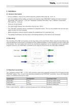
3.1 General information • During installation, observe the profinet assembly guideline PNO order No.: 8.071 /3/ • Use only certified profinet cables, connectors and switches (see "PROFINET Cabling and Interconnection Technology" PNO order No.: 2.252 and "Installation Guideline PROFINET Part 2: Network Components" PNO order No.: 2.252 p2). • Hubs are not permissible. • The cable length between two subscribers may be max. 100 m. • The TWK NBT inclination sensor possesses an integrated switch. This not only enables tree and star topologies but also the linear topology. • Media redundancy protocol...
Open the catalog to page 7
3.4 Status LEDs The inclination sensor has four LEDs. These have the following meaning: 3.5 Project planning A device description file (GSD file) in the XML format GSDML and an image (bitmap) to integrate the inclination sensor into a project planning tool are available in the internet under www.twk.de File name of the GSD file: GSDML-V2.32-TWK-NBT-20180124.xml (The version and date may vary depending on the status of the GSD file) File name of the bitmap: GSDML-0159-8000-TWK_NBT.bmp Project planning using the example of Step7 is explained in the following chapter. Date: 09.04.2019 Page 8 of...
Open the catalog to page 8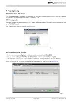
Project planning 4. Project planning 4.1 Simatic Step7 - TIA-Portal This chapter explains the procedure for integrating the TWK NBT inclination sensor into the PROFINET network of a Siemens S7 control system with Step 7 Professional V14. 4.1.1 Prerequisites You have installed and parameterized a F PLC under "Devices & networks" according to your equiment as well as a PROFINET subnet. This is shown here using the example of a CPU1511F: 4.1.2 Installation of the GSD file • In the main menu choose Options, Install general station description file (GSD). • Set the source path to your GSD file, check...
Open the catalog to page 9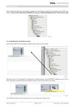
Project planning After installing the GSD file, the hardware catalogue is automatically updated. The inclination sensor NBT is located in Further FIELD DEVICES, PROFINET IO, Sensors, TWK-ELEKTRONIK GmbH, TWK N-Series, NBT. s Other field devices ► S Additional Ethernet devices ▼ IS PROFINET IO ► S Drives ► jj Encoders ► J Gateway ► NO ► S Ident Systems ► IS Network Components ▼ J Sensors ► [SSIEhCNSAG ▼ ^ TOK-ELEKTRONIK GmbH ▼ [S TWK N-Series ▼ IS NBT _ mm_ 4.1.3 Installing the inclination sensor Now drag the NBT from the hardware catalog in the netview of your project. Fig.: 4 Afterwards click...
Open the catalog to page 10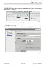
Project planning 4.1.4 Install module To install the inclination sensor module change to the Device view and drag the module "Inclination+status" to the first free slot of the module list. In the properties of the installed module we will set the I/O address and the sensor parameters later on. 4.1.5 Setting the network data Select the inclination sensor in the Device view to show the properties of the PROFINET interface of the NBT.
Open the catalog to page 11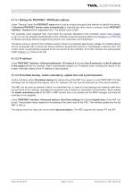
Project planning 4.1.5.1 Setting the PROFINET / PROFIsafe address Under "General" enter the PROFINET name which must be unique throughout the network to identify the device. If Generate PROFINET device name automatically is selected the name which is entered under PROFINET interface - General will be registered here. The default name is NBT. The complete name assigned here must either be manually allocated to the inclination sensor (see Chapter 4.1.8) or it can be assigned automatically by the controller using the topology editor (see Chapter 4.1.7 Planning of "Device exchange without programming...
Open the catalog to page 12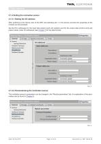
Project planning 4.1.6 Setting the inclination sensor 4.1.6.1 Setting the I/O address After switching to the device view of the NBT and selecting slot 1 in the device overview the properties of the module can be accessed. Set the PLC addresses for the input data (status word and position) and for the output data (control word and preset value) under I/O addresses (see Chapter 5 for the data format). 4.1.6.2 Parameterising the inclination sensor The inclination sensor's parameters can be changed in the "Module parameters" tab. An explanation of the parameters can be found in Chapter 6.
Open the catalog to page 13
Project planning 4.1.7 Planning of "Device exchange without programming device" and "Automatic commissioning" If system restarting without the assignment of a new device name or the IP address is to be possible following the exchange of an installed sesnor with a mint condition device, this must be taken into consideration during project planning. This also applies to "Automatic commissioning", in which the manual and, in the case of larger projects, time-consuming assignment of the device name (as described in Chapter 4.1.8) is avoided during commissioning. The following prerequisites have to...
Open the catalog to page 14All TWK-ELEKTRONIK GmbH catalogs and technical brochures
 Rotary encoder TBN58/C3 manual
50 Pages
 Rotary encoder TBN58/C3
22 Pages
 Rotary encoder TBD Manual
26 Pages
 Rotary encoder TBD
12 Pages
 Rotary encoder TBE58
16 Pages
 Rotary encoder KRP - Manual
19 Pages
 Rotary encoder KRP
7 Pages
 Rotary encoder TBN58/S4 SIL2
22 Pages
 Rotary encoder TBN50/C3 manual
20 Pages
 Rotary encoder TBN50/C3
22 Pages
 Rotary encoder HBN/S3 SIL2
16 Pages
 Product range 2022
64 Pages
 Image brochure TWK
28 Pages
 Inclinometer NBA51
6 Pages
 Incremental encoder FOI
7 Pages
 Rotary encoder TBA42
16 Pages
 Rotary encoder TRA42
16 Pages
 Rotary encoder TRN58/S4 SIL2
22 Pages
 Rotary encoder TRN58/C3 manual
50 Pages
 Rotary encoder TRN58/C3
22 Pages
 Rotary encoder TRN42/S4 SIL2
22 Pages
 Manual TRN50/C3
86 Pages
 Rotary encoder TRN50/C3
22 Pages
 Rotary encoder TRN42/C3 manual
86 Pages
 Rotary encoder TRN42/C3
22 Pages
 Rotary encoder TBN42/S4 SIL2
22 Pages
 Rotary encoder TBN42/C3 manual
86 Pages
 Rotary encoder TBN42/C3
22 Pages
 Rotary encoder TRE58
16 Pages
 Rotary encoder TRT manual
40 Pages
 Rotary encoder TRT
14 Pages
 Switching cam encoder NOCE
14 Pages
 Switching cam encoder NOCA
17 Pages
 Vibration sensor NVT/S3 PLd
12 Pages
 Vibration sensor NVA
12 Pages
 Inclinometer NBN
17 Pages
 Incremental encoder TBI42
6 Pages
 Vibration sensor NVA/S3 PLd
15 Pages
 Rotary transducer PMR411
1 Page
 Rotary encoder TRT/S3 SIL2
13 Pages
 Rotary transducer VP12
1 Page
 Switching cam encoder NOCN
22 Pages
 Inclination sensor NBT
10 Pages
 Inclinometer NBA
17 Pages
 Inclinometer NBT/S3 SIL2/PLd
12 Pages
 Inclinometer NBN/S3 SIL2
13 Pages
 Rotary encoder TBE50
16 Pages
 Rotary encoder HBE
14 Pages
 Rotary encoder TRK manual
18 Pages
 Rotary encoder TRK
11 Pages
 Rotary encoder TMN50 manual
22 Pages
 Rotary encoder TMN50
6 Pages
 Rotary encoder TRK/S3 SIL2
14 Pages
 Rotary encoder TRE42
6 Pages
 Rotary encoder TRE50
6 Pages
 Rotary encoder TRA50
6 Pages
 Rotary encoder TBE42
6 Pages
 Rotary encoder TME42
6 Pages
 Rotary encoder TRD manual
26 Pages
 Rotary encoder TRD
12 Pages
 Rotary encoder TME50
6 Pages
 Rotary encoder TBN36
6 Pages
 Rotary encoder TMA50
6 Pages
 Rotary encoder TMN42 manual
22 Pages
 Rotary encoder TMN42
6 Pages
 Rotary encoder TMA42
6 Pages
 Rotary encoder TBA50
16 Pages
 Rotary encoder TBE36 manual
22 Pages
 Rotary encoder TBE36
6 Pages
 Rotary encoder TBN42
6 Pages
 Rotary encoder TBN37
8 Pages
 Rotary encoder TBA37
7 Pages
 Rotary encoder TBB50
16 Pages
 Rotary encoder PBA12
2 Pages
 Rotary encoder TBA36
6 Pages
 Rotary encoder TKA60
2 Pages
 Rotary encoder TKN46 manual
22 Pages
 Rotary encoder TKN46
7 Pages




- Angular encoder
- Incremental encoder
- Incremental rotary encoder
- Absolute rotary encoder
- Tilt sensor
- Industrial rotary encoder
- Magnetic rotary encoder
- Displacement transducer
- Linear displacement sensor
- Digital inclination sensor
- Aluminum rotary encoder
- Stainless steel rotary encoder
- Single-turn rotary encoder
- MEMS inclination sensor
- Flange rotary encoder
- Ultra-rugged rotary encoder
- Multi-axis tilt sensor
- SSI angular encoder
- Multi-turn rotary encoder
- Analog displacement transducer