
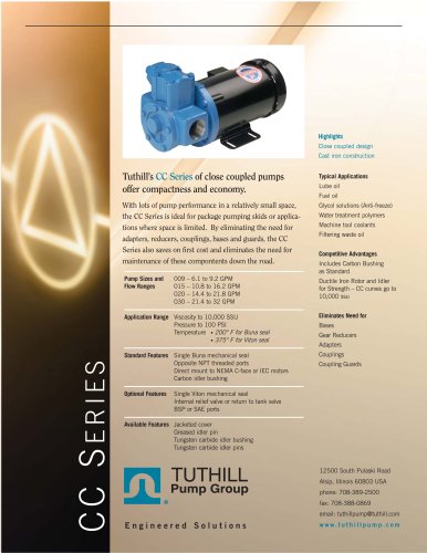
Catalog excerpts

Installation and Service Instructions 1008 & 1010 Size Pumps Excellence at work. Excellence in life.
Open the catalog to page 1
The Pumping Principle Tuthill internal-gear principle is based upon the use of a rotor, idler gear and crescent shaped partition that is cast integrally with the cover. (See accompanying figure). Thus, only two moving parts comprise this efficient pumping element. Power is applied to the rotor and transmitted to the idler gear with which it meshes. The space between the outside diameter of the idler and the inside diameter of the rotor is sealed by the crescent. When the pump is started, there is an increase in volume as the teeth come out of mesh. This creates a partial vacuum, drawing the...
Open the catalog to page 3
pipelines are installed, an inverted “U” bend should be incorporated in the suction line close to the pump to trap liquid in the pump for priming. The suction line must be kept free from air leaks and air pockets. When handling liquids of high viscosity, such as asphalt, heavy gear lubricants, linseed oil, Bunker “C” fuel oil, molasses, etc., the speed of the pumps and the running clearances are important. Consult Tuthill UK, whenever unusual conditions of speed, pressure, vacuum or viscosity are encounted. Before initial start of the pump, it is recommended that some of the liquid to be...
Open the catalog to page 4
WARNING Failure to follow these instructions could result in serious bodily injury or death. Do not attempt to work on any Tuthill pump installation before completing the steps below. Disconnect the drive so that it cannot be started while work is being performed. Review the Material Safety Data Sheet (MSDS) applicable to the liquid being pumped to determine its charaacteristics and the precautions necessary to ensure safe handling. Vent all pressure within the pump through the suction or discharge lines. All Tuthill pumps contain residual ISO 32 lube oil from the factory production test....
Open the catalog to page 5
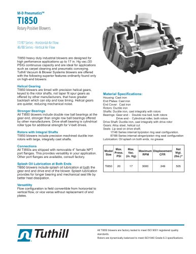
8. The individual parts must now be inspected for damage. The keyway in the end of the rotor must be in good condition and there must not be any deep scratches or grooves on the following surfaces. • The ID surface of the housing and OD of the rotor • The end face of the rotor and OD of the idler • Both faces of the idler • The inside surfaces of the cover including surfaces on the crescent • Areas on the shaft of the rotor were the seal seats Inspection Check cover, housing, rotor and idler for wear, chipped or broken teeth. Drop off in capacity is generally caused by the abrasive action...
Open the catalog to page 6
Consult Tuthill for selecting the proper pump, size of motor, and pipeline size for your job with the following information. • Capacity required with max/min liquid temperatures when entering the pump • The viscosity at the minimum temperature • Total length of suction pipe and discharge pipe • Suction lift and height to which the pump must force the liquid 1008 Parts List Item
Open the catalog to page 7
Field Checklist What to look for when 1. No Oil is delivered • Suction lift too high for vapour pressures of liquid pumped • While Tuthill Pumps will develop as high as 27 inches of vacuum, it is wise to reduce the vacuum to a minimum • Bad leaks in suction line or port passages can be detected by submerging pressure line from discharge side of pump into a pail of oil where the air will be seen in the form of bubbles • Wrong direction of shaft rotation (In "R" models, check position of cover boss) • Pump shaft not rotating (Check coupling or drive) • Relief valve setting too low...
Open the catalog to page 8
The maximum vacuum at the pump suction should never exceed 15 inches of mercury. It is necessary to keep below 15 inches not because of the inability of the pump to handle a higher vacuum, but primarily because of the vaporization that is liable to take place at a higher vacuum. Vaporization caused by higher vacuums will generally result in capacity drop-off. 3. Pump Works Spasmodically • Leaky suction lines • Suction lift too high • Air or vapour in liquid • Coupling slipping on pump shaft. 4. Pump Wastes Power • Pressure too high • Liquid more viscous than desired • Suction or discharge...
Open the catalog to page 9All Tuthill catalogs and technical brochures
-
 HD Series Pumps
39 Pages
-
 4000 Series Pumps
18 Pages
-
 Product Line Brochure
6 Pages
-
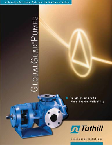
 GlobalGear® Series
6 Pages
-
 Tuthill Plastic Group
6 Pages
-
 D Series Pump
3 Pages
-
 Performance Curves - 1000 Series
16 Pages
-
 Engineering Data Pack - M Series
23 Pages
-
 FR1118P10 In-line Meter
1 Pages
-
 Tuthill Precision Meters
8 Pages
-
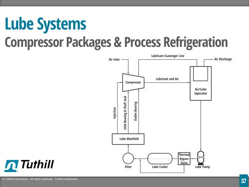 Presentation - Lube Systems
9 Pages
-
 L & C SERIES
6 Pages
-
 Heavy Duty Series
6 Pages
-
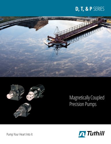 2016 D, T, & P SERIES
6 Pages
-
 1000 SERIES
6 Pages
-
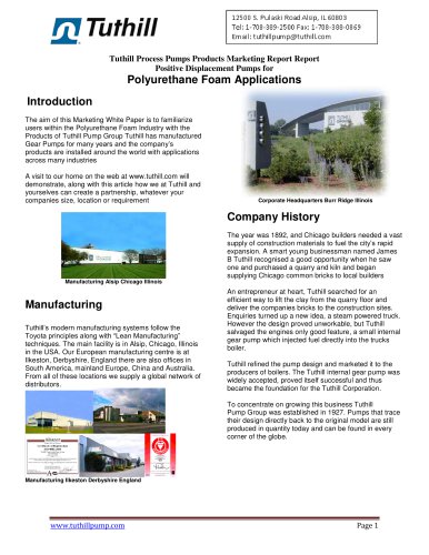
 White Paper - Pulp & Paper
2 Pages
-
 White Paper - Asphalt
3 Pages
-
 TI850 TH-063
2 Pages
-
 QX TH-094
2 Pages
-
 PD Plus 9000 TH-052
2 Pages
-
 PD Plus 7000 TH-051
2 Pages
-
 PD Plus 5500 TH-050
2 Pages
-
 PD Plus 3200 TH-048
2 Pages
-
 PD Plus 1200 TH-047
2 Pages
-
 MD Pneumatics blower
2 Pages
-
 PneuPak TH-056
2 Pages
-
 PneuMax II TH-055
2 Pages
-
 Equalizer RM TH-045
2 Pages
-
 Equalizer DF TH-046
2 Pages
-
 Competitor SL TH-044
2 Pages
-
 Competitor Plus TH-043
2 Pages
-
 TuffSeall
2 Pages
-
 M Series
2 Pages
-
 HD Series
6 Pages
-
 Full Line
6 Pages
-
 Vacuum Pumps Brochure TH-004
8 Pages
-
 atlantic fluidics
16 Pages
-
 KDS Dry Screw Vacuum Pump
3 Pages
-
 Vacuum Pump Selector Guide
6 Pages
-
 KTLP/VFP Series
2 Pages
-
 Kinney® KMBD Vacuum Boosters
2 Pages
-
 Liquid Ring Vacuum Pumps
16 Pages
-
 Rotary Piston Vacuum Pumps
18 Pages
-
 Process Gear pumps
6 Pages
-
 T950H Brochure
4 Pages
-
 T650 Product Brochure
4 Pages
-
 Qube Product Brochure
6 Pages


Archived catalogs
-
 GlobalGear® Series
6 Pages
-
 2015 D, T, & P Series
14 Pages
-
 Series 1000
6 Pages
-
 T850/T1050 Truck Blowers
4 Pages
