- Catalogs
- Tsubakimoto Chain
- Tsubaki Reducer For Servo Motors Tsubaki TERVO
- Company
- Products
- Catalogs
- News & Trends
- Exhibitions
Tsubaki Reducer For Servo Motors Tsubaki TERVO
1 /44Pages

Tsubaki Reducer For Servo Motors Tsubaki TERVO
1 /44Pages
Catalog excerpts

REDUCER FOR SERVO MOTORS TSUBAKI TERVO HMTK H SWJMK SWMK ・ EWJMK EWMK
Open the catalog to page 1
Tsubaki’s TERVO converts equipment to servo drive. Wide-ranging lineup of gears • Helical gears • Hypoid gears • Worm gears
Open the catalog to page 2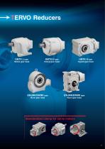
TERVO Reducers Helical gear head Helical gear head Hypoid gear head SWJMK/SWMK type EWJMK/EWMK type Worm gear head Worm gear head Standardized clamp for servo motors
Open the catalog to page 3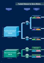
Rich variety of shaft styles and various mounting methods TERVO Backlash: 10 to 70 arcmin ’ Reduction ratio Highly precise and compact PAT-B Backlash: 3 to 9 arcmin Reduction ratio Tsubaki Reducer for Servo Motors Arrangement Gears —Hypoid gear Highefficiency Low height Right angle shafts Parallel shafts Right angle shafts Parallel shafts Worm gear Heavy duty Helical gear Highefficiency ra“ations Bevel gear Helical planetary gear High precision! Helical planetary gear High precision!
Open the catalog to page 4
Selection Guide Type Model range Hollow shaft Hypoid gear head HMTK H Solid shaft Hypoid gear head HMTK U Hollow shaft Worm gear head SWJMK, SWMK Solid shaft Worm gear head EWJMK, EWMK Solid shaft Helical gear head GMTK U, GMTK F Selection Guide Output shaft style Face mount, flange installation Solid shaft Foot mount Solid shaft Helical gear head GMTK L High precision planetary gearbox PAT-B Series Right angle type Solid shaft High precision planetary gearbox PAT-B Series In line type
Open the catalog to page 5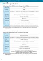
Standard Specifications and Models ■ Standard Specifications1. Hypoid gear head HMTK type and helical gear head GMTK type Reducer Note) Regarding the ambient conditions, use the product within the ranges supported by the servo motor on which the product is mounted. Note) Regarding the ambient conditions, use the product within the ranges supported by the servo motor on which the product is mounted.
Open the catalog to page 6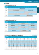
■ Models1. Hypoid gear head HMTK type 0.4kW
Open the catalog to page 7
Sizing 1. Conditions (1) Motion profile Output shaft speed nT : Maximum output shaft speed (r/min) t1 : Acceleration time (s) t2 : Constant speed time (s) Output torque (2) Load moment of inertia Ir Use the tables on page 13 to calculate Ir, the load moment of inertia on the output shaft of the reducer. (3) Acceleration torque Ta and deceleration torque Tb Ir Acceleration torque Ta =△Ta+Tc △na : Speed difference (r/min) Deceleration torque Tb =△Tb−Tc △Tb = 2πI r×△nb 60×t3 △nb : Speed difference (r/min) △nb = nT−no (4) Constant speed torque Tc Workpiece M1 (kg) μ: Coefficient of friction of...
Open the catalog to page 8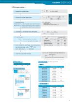
TSUBAKI TSRVQ 2. Sizing procedure (1) Calculate the reduction ratio i. I (2) Calculate the average output torque. (3) Determine the size. Average torque Tave.< rated torque of the output shaft of the reducer Maximum torque Ta< rated torque of the output shaft of the reducer x series factor fs T b< rated torque of the output shaft of the reducer x series factor fs (3) fs: Series factor GMTK-HMTK : 1.4 EWJMK-EWMK-SWJMK-SWMK : 1.0 (4) Calculate nave., the average output shaft speed. Ih°ii°w output shaft| Q: See the tables to the right for the standard length. For hollow output shafts Driven shaft...
Open the catalog to page 9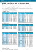
■ Motor Mount Codes (Hypoid and Helical Gear Heads) IhedlmensionsjSorrespondingJo,theservojmotorsoivarjouscompaniesareshownasmountcodes. The product has been set with the capacities of each motor as standards, but be sure to use the product within the transfer capacity range of each gear head. Note) The mount code interaction tables are representative examples that are current as of December 2012. It may be possible to support servo motors not shown in the tables, so contact us for details. Note) The servo motor specifications may be changed depending on the situation of the motor manufacturer,...
Open the catalog to page 10
4. SANYO DENKI P Series servo motors Motor capacity Motor capacity 5. PanasonicMINAS A5 Series servo motors Motor capacity TBL-i II Series servo motors TBL-i Series servo motors Motor capacity Motor capacity ◎ : Standard package △ : Supported as necessary Regarding items indicated by the symbol, the reducer's no-load loss in relation to the motor output torque is large, so operation may not be possible depending on
Open the catalog to page 11
■ Motor Mount Codes (Worm Gear Heads) Ihe_dimensionscorrespondingJtolheservomotorsolvariouscompaniesj,reshowaa,smountcodes. Check the mount code corresponding to the servo motor being used, and then select a gear head whose size and reduction ratio match the operating conditions according to the information found under "Standard Mount Codes Categorized by Worm Gear Heads" and "Transfer Capacity Table" for each series. Be sure to select a model within the performance range of each gear head corresponding to the load conditions. Note) The mount code interaction tables are representative examples...
Open the catalog to page 12
2. Yaskawa Electric Z -V Series servo motors Z III Series servo motors Motor capacity Rated speed Model no. Mount code TBL-i II Series servo motors Motor capacity
Open the catalog to page 13
Determining the moment of inertia 1. Moment of inertia of the rotating body Moment of inertia calculation SI units Moving body When the center of movement is the shaft GD2 calculation (gravitational units) When the center of movement is not the shaft 2. Equivalent moment of inertia of a body moving in parallel V(m/min) n: Number of motor rotations in relation to V (r/min) n: Motor speed (r/min) in relation to V
Open the catalog to page 14
TSUBAKI HMTK HMTK Type Hypoid Gear Head Hypoid Gear Head Contents Model Number Designation ······························ Page 15 Transfer Capacity Table····································· Page 15 Dimensions ·································
Open the catalog to page 15All Tsubakimoto Chain catalogs and technical brochures
 TSUBAKI DIRVE CHAINS & SPROCKETS
234 Pages
 TIMING beltand pulleys
72 Pages
 REDUCER FOR SERVO MOTORS TERVO
42 Pages
 TSUBAKI COUPLINGS
120 Pages
 Tsubaki Miter Gear Box
64 Pages
 Drive Chains & Sprockets
219 Pages
 Cam Clutch BR-HT Series
8 Pages
 Tsubaki Couplings
120 Pages
 Tsubaki Lambda Chain Leaflet
6 Pages
 Tsubaki Pin Gear Drive Units
6 Pages
 Tsubaki gear motors 40 W - 5.5 kW
268 Pages
 Titan Series Chain
4 Pages
 TRAXLINE Cables for Motion
88 Pages
 Power-Lock
88 Pages
 SJ3 Sealed Joint Technology
2 Pages
 TKA Series Plastic Cable Carrier
21 Pages
 Tsubaki Smart Tooth
2 Pages
 Tsubaki Cam Clutch Box Series
16 Pages
 Tsubaki Cam Clutch
92 Pages
 Tsubaki Pin Oven Chain
4 Pages
 Top Chain Engineering Manual
76 Pages
 Tsubaki Pin Gear Drive Units
16 Pages
 Tsubaki Cleanveyor
12 Pages
 Tsubaki Gripper Chain
6 Pages
 Tsubaki Top Chain
246 Pages
 Tsubaki Small Size Conveyor Chains
168 Pages
 Tsubaki Palm Oil Mill Chain
2 Pages
 Tsubaki PC Chain Brochure
12 Pages


Archived catalogs
 Tsubaki Custom Made Chain
90 Pages
 ZIP CHAIN ACTUATOR
56 Pages


- Cylinder
- Actuator
- Electric gearmotor
- Linear actuator
- Power transmission belt
- Articulated telesocpic boom lift
- Precision gearhead
- Tsubaki conveyor belt
- Hydraulic cylinder
- Tsubaki right angle gear reducer
- Compact gearhead
- Solid-shaft gearhead
- Flexible coupling
- Tsubaki shaft coupling
- Gear train gear reducer
- Hollow-shaft gearhead
- Lifting system
- Protection relay
- Compact actuator
- Transmission gearhead