
- Catalogs
- Tsubakimoto Chain
- Power Cylinder Linipower & Linispeed Jack


- Company
- Products
- Catalogs
- News & Trends
- Exhibitions
Power Cylinder Linipower & Linispeed Jack

Power Cylinder Linipower & Linispeed Jack
The document provides comprehensive information on Tsubaki's Linear Motion Power Cylinders, focusing on the Linipower® and Linispeed Jack series. It includes details on models, specifications, applications, and environmental considerations.
The Power Cylinder series includes various types such as the F, G, T, and U series, each offering unique features like wet slip clutches and thrust detection systems. The Linipower Jack is intended for indoor use, while the Power Cylinder is suitable for outdoor applications.
Power Cylinders offer thrust capacities from 4.9kN to 313kN, designed for pushing or pulling loads. They are energy-efficient, reducing CO² emissions by up to 80% compared to hydraulic or pneumatic cylinders.
These cylinders are used in applications like opening and closing mechanisms, elevation devices, and positioning systems, suitable for industries requiring reliable load handling and precise positioning.
The Power Cylinder is eco-friendly, significantly reducing CO² emissions and electricity usage, operating cleanly without oil leaks, and suitable for high places and adverse environments.
Technical specifications include rated thrust, speed, stroke, and motor capacity. The use of ball screws and nuts enhances transmission efficiency and longevity.
The U series is noted for its lightweight and compact design, offering cost performance and a complete lineup for replacing hydraulic cylinders.
Power Cylinders are easy to install and operate, requiring only electrical wiring. They are fully sealed for outdoor use and can be equipped with various position detecting devices.
Tsubaki's Power Cylinders provide a versatile and eco-friendly solution for linear motion applications, offering a range of models to suit different industrial needs.
The document outlines the selection process for power cylinders, including determining the model based on thrust, speed, stroke, and operational frequency. It provides a detailed procedure for calculating the annual traveling distance and expected life of the cylinders.
Safety features include wet slip clutches and thrust detecting mechanisms to handle overloads. The document advises on using shock relays for electrical overload detection and provides guidelines for setting up limit switches for accurate stopping.
Tables and charts assist in selecting the appropriate power cylinder model based on expected traveling distance and load conditions. Recommendations for handling radial and unbalanced loads are provided.
The expected life of the power cylinders is discussed in terms of operation cycles and traveling distance. Proper lubrication and maintenance are crucial for extending the life of components.
Several tables provide reference values for coasting distance, stop accuracy, and allowable mass, ensuring correct application and performance in various scenarios.
Detailed circuit diagrams for brake motors and power modules are provided, highlighting the importance of removing short pieces before use and applying normal power source voltage to specific terminals.
Installation can be in any direction, using trunnion or clevis mounts. Grease application is crucial for trunnion pins and ball screws, with specific instructions for greasing procedures.
Designated greases are specified for different components, with lubrication cycles based on operating frequency.
The document discusses the U Series N type, compatible with T Series mounting dimensions, offering extended life and reduced replacement frequency.
Guidelines include applying grease to mounting components and considering bearings for swinging parts. Outdoor use requires protective covers under adverse conditions.
Limit switches should regulate stroke ends, and exceeding stroke limits can cause damage. High-speed types require careful limit switch adjustments to prevent override.
This section outlines the T Series' features, including thrust options, safety mechanisms, and available options for stroke adjustment and position detection.
The document describes the structure of TB and TC types, including components like ball screws and limit switches, specifying environmental conditions for use.
The document outlines the specifications for power cylinders, emphasizing their use in outdoor environments and the need for protective measures against adverse conditions.
Key usage guidelines include regulating stroke ends with a limit switch and ensuring operation within the specified stroke range to prevent breakage.
The power cylinders are designed for durability and long life, featuring a ball screw with high load capacity and a thrust detecting mechanism for overload protection.
Selection procedures involve determining the operation factor based on load characteristics and calculating the annual traveling distance.
Safety features include a thrust detecting mechanism to protect against overloads. Regular maintenance and adherence to usage guidelines are crucial for ensuring longevity and safe operation.
The document outlines the electrical specifications for a power module, including the use of an MCB with a contact capacity of 250V AC, 7A or more.
Installation instructions include using a trunnion or clevis mount and applying grease to specific parts.
The document provides methods for adjusting external limit switches and variations in mounting.
Several cautions are provided, including the need for anti-rod rotation and the regulation of stroke ends by limit switches.
The document describes easy wiring specifications that prevent damage from excessive torque and stroke.
The document provides detailed specifications and options for the LPG series power cylinders, emphasizing simplicity, safety, and cost-effectiveness.
The power cylinders are available in various thrust capacities ranging from 100N to 6.00kN, featuring a compact design with a right-angle configuration.
Several options enhance the functionality of the power cylinders, including stroke adjustment external limit switches and overload detection units.
The document provides a comprehensive model designation system, detailing thrust, speed, and voltage options.
The power cylinders are designed for outdoor use, withstanding temperatures from -5°C to 40°C and relative humidity of 85% or less.
The document includes graphs illustrating the relationship between thrust, speed, and current values for different models and power sources.
Detailed dimensions and installation guidelines are provided for each model, including options for bellows and external limit switches.
Position detection units are available with internal limit switches and potentiometers, although they cannot be used simultaneously.
The LPG series power cylinders offer a versatile and reliable solution for various applications, with a focus on reducing wiring complexity and enhancing safety.
The document describes the specifications and applications of a new type of power cylinder, specifically designed for press contact stop and motorized air cylinders.
The power cylinders are available in various models with different rated thrusts and speeds.
The SpeedMech system allows the cylinder to stop without a limit switch by using a spring in the actuating part and a CDS board in the terminal box.
The document outlines various applications where the SpeedMech power cylinders can replace pneumatic and hydraulic cylinders.
The document provides guidelines for selecting the appropriate model based on thrust and speed requirements.
Users are advised to consider environmental conditions and ensure proper installation and maintenance to avoid operational issues.
The document outlines the use of four synchronized jacks for lifting operations at room temperature with low dust conditions.
The document provides formulas for calculating the required input torque and rotation speed for the servomotor and jacks.
Regular lubrication and oil changes are recommended, with specific intervals based on operation frequency.
Ensure no lateral loads are applied to the jacks, and use guides if necessary.
The document includes tables and graphs for calculating allowable buckling loads and expected travel distances.
The document provides detailed specifications and options for various types of jacks, including machine screw, ball screw, and high lead ball screw types.
The document lists specifications for different jack models, including frame size, basic capacity, screw outer diameter, gear ratio, stroke, lubrication, color, environment, anti-rotation, and various end fittings.
- JWM (Machine Screw Type): Suitable for low speed, low frequency operations, featuring a self-locking mechanism.
- JWB (Ball Screw Type): Designed for high speed, high frequency operations, offering high efficiency and extended life.
- JWH (High Lead Ball Screw Type): Capable of super high speed and quiet operation, requiring a brake unit as self-lock is not provided.
The document includes technical notes on selecting the appropriate Linipower Jack, considering factors like load conditions, screw shaft speed, allowable load, and wear life.
A step-by-step guide is provided for selecting the appropriate jack, including calculating adjusted load, verifying buckling load, confirming input rpm, and selecting options based on specific needs.
An example of a four-jack synchronous drive system is provided, detailing the selection process, including load calculations, speed requirements, and drive unit selection.
The document outlines the process for selecting drive units and gearboxes, considering required torque and input rpm, and ensuring compatibility with the jack system.
- Gear boxes are specified for different configurations: ED4M for jacks and ED6M for gearmotors.
- Couplings are selected based on input torque, shaft diameters, and the number of required units.
- The rated input capacity for JWB050USH3 is 0.58 kW, which is less than the maximum of 2.2 kW.
- Wear life is calculated based on expected travel distance, with a suitable jack number identified as JWB050.
- Graphs illustrate the relationship between screw shaft speed and allowable load for different frame numbers.
- Allowable buckling load graphs help determine the correct frame number based on specific buckling loads and installation conditions.
- Overhang load calculations ensure that applied loads are within allowable limits.
- Screw shaft rpm must be verified to ensure it remains within rated values.
The document outlines specifications for various models of the JWH series, including JWH010, JWH025, JWH050, JWH100, JWH150, and JWH200.
Installation notes emphasize the importance of considering return tube measurements and the potential variation in ball nut return tube and travel flange openings.
The duty cycle for the JWH High Lead Screw Type is within 30% ED, meaning it operates for a maximum of 30% of a 30-minute interval.
It is recommended to maintain activating torque for the drive unit at 200% above the required torque.
The document includes detailed tables of dimensions for each model, specifying minimum and maximum values for various parameters.
The JWH (High Lead Screw Type) jack is equipped with a fall stop mechanism.
When installing sprockets, gears, or belts, ensure that the overhang load (OHL) is within allowable limits.
Manual operation from the input shaft with load applied is dangerous and should be avoided.
The document includes detailed technical data on various models, including motor capacities, gear ratios, shaft speeds, and thrust values.
This document provides comprehensive technical specifications, installation guidelines, and usage precautions for the JWH (High Lead Screw Type) jack.
This document provides detailed specifications and operational guidelines for various motorized jack systems, including machine screw, ball screw, and high lead ball screw types.
The document lists motor capacities ranging from 0.2kW to 3.7kW, with corresponding shaft speeds and thrust values for different jack types.
Motors are available in 200V and 400V configurations, with protection ratings of IP55 and insulation class E.
Various stroke control options are available, including limit switches, potentiometers, and rotary encoders.
The document emphasizes the importance of correct installation to avoid exceeding thrust capacities and to ensure proper operation.
The document highlights the benefits of using hypoid and servo motor types for space-saving and precise control.
The document outlines specifications for various components such as potentiometer control options, rotary encoders, clevis and trunnion mounting adapters, hand wheels, safety caps, and bellows.
Instructions are provided for setting maximum and minimum stroke positions using limit switches and meter relays.
The document references JIS C1102 standards and provides recommendations for bolt sizes and tightening agents.
Guidelines are provided for the installation of jacks, including orientation, bolt tightening, and the use of oil pans.
Safety caps are recommended to prevent accidents and dust generation.
The document includes tables and figures detailing measurements for clevis and trunnion adapters, hand wheels, and safety caps.
Visible particles due to wear and tear of the screw unit are noted.
Table 1 lists recommended greases, including TSUBAKI JWGS100G and others.
Consider jack ratings and ensure loads fall within rated capacity.
Definitions are provided for terms such as Basic Capacity, Screw Lead, Stroke, Worm Ratio, Overall Efficiency, and more.
Linipower Jack LD Type is suitable for clean room systems, minimizing dust and rust.
Guidance is provided for selecting reducers, gearboxes, couplings, and drive sources.
Catalog excerpts

TSUBAKI POWER CYLINDER LINIPOWER® & LINISPEED JACK LINEAR MOTION
Open the catalog to page 1
Series lineup Power Cylinder With wet slip clutch LPUC type With thrust detection system LPTB type With wet slip clutch LPTC type With thrust detection system LPTB type Multi series Basic type LPTC type With thrust detection system Power Cylinder Worm series LPGA type Basic type LPGB type With wet slip clutch LPGC type Straight Parallel Parallel Straight With thrust detection system Servo type Linear actuator Mini series Eco series Linispeed Jack Linispeed Jack Differences between and how to select the Power Cylinder and Linipower Jack SJ (High-lead ball screw) Power Cylinder Linipower Jack •...
Open the catalog to page 2
Basic specifications list Capacity range - Multi series - Worm series - Mini series -
Open the catalog to page 3
Application Solution Power Cylinders were developed over 40 years ago, and have been used across a variety of industries by a wide range of customers. By taking advantage of our accumulated experience, we have continued to develop new products as well as upgrade technologies, and proactively address environmental issues to create our present series. We will continue to create products which are customer-friendly, taking the environment into consideration. For heat treatment furnace/door opening and closing For CT scanning/bed elevation For pusher/roller conveyor For machine tools/door opening...
Open the catalog to page 4
electrical wiring Clean operation is possible because there Unlike hydraulic cylinders, operation at a All you need for operation is electrical is no oil leak. high place and under adverse environment wiring. is easier, because power cylinder does not require extra components installation. Eco-Friendly The Power Cylinder has been recognized as a power-saving product by LCA (Life Cycle Assessment). In addition to its energy-saving feature, CO2 emissions can be significantly reduced compared with air cylinders and hydraulic cylinders. Electrical UsageComparison of electricity per 1set (kWh/year)...
Open the catalog to page 5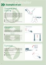
Opening and closing Various types of opening and closing can be performed by changing the linear motion of power cylinders into turning force through link mechanisms or by using the linear motion as it is. G/T/U series (C type) that can press at the end are suitable. Those with a position detecting unit are used to indicate the degree of opening. • Opening and closing of hopper gates • Opening and closing of switching dampers • Opening and closing of the lids of drying furnaces, incinerators, various kilns, etc. Elevation Various types of elevation can be performed by using the linear motion...
Open the catalog to page 6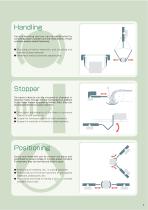
Handling Various handling devices can be established by combining power cylinders and link mechanisms. Power cylinders enable reliable fastening. • Chucking of cotton materials, and chucking and transfer of steel materials • Handling of various automatic apparatuses Stopper Conveyed objects can be stopped or changed in direction mainly through the link mechanisms in addition to the linear motion of power cylinders. Also, they can be stopped directly by power cylinders. • Directional adjustments of the flows of conveyed objects on belt conveyors • Stopper for conveyed objects on roller conveyors...
Open the catalog to page 7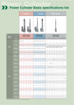
Power Cylinder Power Cylinder Basic specifications list U series Rated thrust Multi series The cylinder speed varies depending on the input rotation speed. Refer to page 67 for details.
Open the catalog to page 8
Contact Tsubaki
Open the catalog to page 9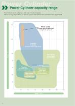
Power Cylinder Power Cylinder capacity range Power Cylinders can be used across a wide range of thrusts and speeds. Refer to the image diagram below and select the optimum model from the basic specifications list on pages 7 and 8. Worm series AC power source, replacement for hydraulic cylinders AC power source, large thrust Eco series servo type For servomotor AC power source, medium thrust F series DC power source, small and medium thrust Eco series CDS type AC power source, for press stopping Single-phase, 3-phase power source
Open the catalog to page 10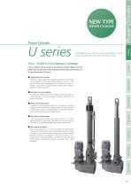
Power Cylinder New flagship power cylinder (Successor model of T series Power Cylinders with more than 6 tons rated thrust) Power Cylinder POWER CYLINDER Power cylinder that succeeds in providing a smaller, lighter unit with better cost performance while maintaining the same performance of the previous model (T series). Thanks to newly developed special ball screws and bearings, we succeeded in reducing the total length by a max. of 11% and the mass 40% compared with the previous model (T series). The smaller size and lighter weight make it easy to replace hydraulic cylinders. Multi series ●...
Open the catalog to page 11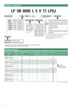
LP UB 6000 L 5 V T1 LPUJ Power cylinder Motor Option Option code Nominal stroke Voltage code *The above values are examples of indication. L : two external limit switches for stroke adjustment*1 With L3 : three external limit switches for stroke adjustment*2 With K2,K4 Position detecting internal limit switch : P : Potentiometer R : Rotary encoder C : Clevis*3 U : type end fitting (blank: standard)*4 U J : Bellows*5 *1: This cylinder may be damaged during overstrokes. At minimum, we recommend attaching this OP (for position control). *2: Please specify 4 or more mountings separately. *3: Cannot...
Open the catalog to page 12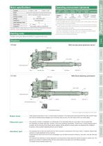
1) The bellows option is recommended in dusty areas. 2) Units can treated with paint or protective coating for use in areas subject to sea winds and salt. Contact us for more information. 3) All models have fully sealed construction for use in normal outdoor conditions. However, protective covering must be furnished in harsh environments that are subject to constant water, steam, or snowfall. For use in environments that reach 40°C or more, furnish an insulation cover. Never use in flammable environments. There is a risk of explosions and fire hazards. Do not use in areas subject to vibration...
Open the catalog to page 13
Classification of usage for LPUB and LPUC types Both types of the power cylinders have the same basic functions (thrust, speed, stroke), however, each has its feature as regards the mechanism. Read the following to select the optimum type. UB type ● With wet slip clutch [Wet slip clutch] The screw shaft end of the reduction part incorporates a slip clutch which operates stably in grease as a safety device. Adoption of special lining exerts a protective function even at the time of overload or stroke overextension. * When overload is electrically detected, use in combination with our shock relay...
Open the catalog to page 14All Tsubakimoto Chain catalogs and technical brochures
 TSUBAKI DIRVE CHAINS & SPROCKETS
234 Pages
 TIMING beltand pulleys
72 Pages
 REDUCER FOR SERVO MOTORS TERVO
42 Pages
 TSUBAKI COUPLINGS
120 Pages
 Tsubaki Miter Gear Box
64 Pages
 Drive Chains & Sprockets
219 Pages
 Cam Clutch BR-HT Series
8 Pages
 Tsubaki Couplings
120 Pages
 Tsubaki Lambda Chain Leaflet
6 Pages
 Tsubaki Pin Gear Drive Units
6 Pages
 Tsubaki gear motors 40 W - 5.5 kW
268 Pages
 Titan Series Chain
4 Pages
 TRAXLINE Cables for Motion
88 Pages
 Power-Lock
88 Pages
 SJ3 Sealed Joint Technology
2 Pages
 TKA Series Plastic Cable Carrier
21 Pages
 Tsubaki Smart Tooth
2 Pages
 Tsubaki Cam Clutch Box Series
16 Pages
 Tsubaki Cam Clutch
92 Pages
 Tsubaki Pin Oven Chain
4 Pages
 Top Chain Engineering Manual
76 Pages
 Tsubaki Pin Gear Drive Units
16 Pages
 Tsubaki Cleanveyor
12 Pages
 Tsubaki Gripper Chain
6 Pages
 Tsubaki Top Chain
246 Pages
 Tsubaki Small Size Conveyor Chains
168 Pages
 Tsubaki Palm Oil Mill Chain
2 Pages
 Tsubaki PC Chain Brochure
12 Pages


Archived catalogs
 Tsubaki Custom Made Chain
90 Pages
 ZIP CHAIN ACTUATOR
56 Pages


- Electric gearmotor
- Linear actuator
- Power transmission belt
- Articulated telesocpic boom lift
- Tsubaki conveyor belt
- Precision gearhead
- Tsubaki right angle gear reducer
- Compact gearhead
- Solid-shaft gearhead
- Hollow-shaft gearhead
- Flexible coupling
- Gear train gear reducer
- Tsubaki shaft coupling
- Lifting system
- Protection relay
- Transmission gearhead
- Compact actuator