
- Catalogs
- Tsubakimoto Chain
- Overload protection and control devices


- Company
- Products
- Catalogs
- News & Trends
- Exhibitions
Overload protection and control devices

Overload protection and control devices
- Torque Limiter: Available in friction type, it prevents overload by slipping at a preset torque.
- Shock Guard: Comes in various series (TGB, TGE, TGX, etc.), offering automatic reset and protection against overloads in different applications.
- Axial Guard: Provides overload protection in the axial direction, suitable for applications like pushers.
- Shock Relay: Monitors motor current and provides overload protection with remote monitoring capabilities.
- Shock Monitor: Detects overloads and tool breakage, suitable for high-precision machining applications.
- Torque Keeper and MINI-KEEPER: Mechanical slipping clutches and brakes that provide stable slip torque and are ideal for applications requiring continuous slip.
- Set torque ranges from 0.294 to 9310Nm, with maximum RPMs varying by device type.
- Motor capacities for Shock Relay and Shock Monitor range from AC200V 0.1 to 110kW and AC400V 0.1 to 132kW.
The document outlines various series of Shock Guards, each tailored for specific applications:
- TGB Series: General use, economical, and easy to operate.
- TGE Series: Compact design suitable for small-diameter sprockets.
- TGX Series: High precision and rigidity, ideal for precision positioning.
- TGF Series: Excellent reset position accuracy, ideal for indexers.
- TGM Series: Sealed construction for wet, oily, and dusty environments.
- TGZ Series: ON-OFF clutch with simple layout.
- TGK Series: Air clutch structure for remote torque adjustment.
Selection Guide: The document provides a selection guide to help users choose the appropriate safety device based on their machinery's requirements, such as precision, automatic reset capability, and environmental conditions.
Procedures and Recommendations:
- Setting Trip Torque: Guidelines for setting the trip torque based on machine strength and load.
- High RPM Considerations: Special considerations for machines with high RPM or large load inertia.
- Model Selection: Instructions for choosing the correct model based on calculated trip torque and bore diameter.
- Maintenance: Regular maintenance recommendations, including greasing intervals and inspection procedures for sprockets and roller chains.
Technical Data:
The document includes technical data such as torque ranges, bore ranges, and repetitive motion torque accuracy for each series. It also provides a detailed explanation of terms like backlash, reset methods, and overload detection.
Safety Precautions:
Users are advised to install Shock Guards near potential overload points and to avoid using them with human transportation or lifting devices without proper precautions.
Additional Components:
The TG Sensor is highlighted as an overload detecting sensor that can be used with various Shock Guard series to stop the motor and signal an alarm in case of overload.
- Axis Installation: Recommended shaft diameter tolerance is h7. Use JIS 1301-1996 parallel key with clearance between key and keyway. Tighten bolts in specified places for cam actuating plate installation. Use tap holes on mounting seat side if set screws cannot be used.
- Drive Member Installation: Use 3 mounting seats and tighten bolts with specified torque for sprockets, pulleys, gears, and couplings. Consult TEM for combining TSUBAKI Power Lock with non-backlash coupling.
- Resetting: Automatic reset system. Stop rotation and remove overload cause before resetting. Reset with input rpm less than 50r/min.
- Grease: Pre-packed with high-quality grease; additional greasing not necessary under normal conditions.
- Overload Protection: Drive ball disengages during overload, allowing free rotation.
- ON-OFF Clutch: Mechanical type clutch with easy torque adjustment and monitoring.
- Handling: Confirm indicators are set at zero upon receipt. Disassemble carefully to avoid losing parts.
- Machining: Follow keyway specifications and centering guidelines for bore finishing.
- Resetting: Align driven flange hole with hub setscrew position for correct phase.
- Maintenance: Grease drive ball and ball cage annually or every thousand trips.
- Tables: Include specifications for bolt screw-in length, tightening torque, and model-specific parameters.
- Diagrams: Illustrate installation examples, circuit examples, and component layouts.
Ensure not to exceed the torque indicator's maximum value when adjusting the nut or bolt, as this can lock the position and prevent the disk spring from bending.
Shock Guard TGXZ Series:
This series is non-backlash and complete release type, suitable for high-speed applications up to 1800 r/min. For torque settings of 451 N・m and above, contact TEM.
Pneumatic Torque Adjustment Mechanism:
The TGK series features a one-position type air clutch ON-OFF mechanism, allowing remote torque adjustment by regulating air pressure. It combines overload protection with an air clutch function.
Construction and Operating Principles of TGK Series:
The TGK series transfers force via drive balls between the hub and drive plate. Torque can be adjusted during operation by changing air pressure. In case of overload, the drive balls disengage to protect the machine.
Clutch Mechanism:
To disconnect the drive source, stop air supply, allowing the built-in spring to disengage the drive balls. The system resets automatically upon air supply resumption.
Transmissible Capacity and Dimensions:
Detailed specifications for models TGK20-A2, TGK30-A2, and TGK45-A2 are provided, including torque ranges, maximum rpm, and air pressure requirements.
Torque Adjustment and Air Control System:
Torque is adjusted by air pressure, with a range of 0.14 to 0.55 MPa. The system allows for torque changes during operation, enhancing machine protection.
Electrical Diagram and Basic Operation:
The system includes components like air filters, regulators, and solenoid valves. The motor operation is controlled via start/stop buttons and a selecting switch, with overload protection through limit switches.
- Model Numbers: TGA65, TGA150, TGA250, TGA350.
- Max Set Load: 65, 150, 250, 350 kgf.
- Components: Slide shaft, case, side plate, drive ball, plate, disk spring, hexagon socket head set screw, adjustable screw.
- Dimensions and Load Capacity: Detailed in diagrams with specific measurements for each model.
- Ensure the Axial Guard is installed on the driven side where overload is most likely.
- Use adhesive for metal on threaded portions to prevent loosening.
- Do not fix both the slide shaft and case side rigidly to avoid malfunction.
- Apply grease to prevent interference between guide sleeve and guide shaft.
- Use the No. of rotations indicator and angle indicator to set the trip load.
- Loosen the hexagon socket head set screw before adjusting the load.
- Perform a load trip test to ensure optimal settings.
- Stop the machine and remove the cause of overload before resetting.
- Reset automatically by reversing the load direction using low RPM.
- Do not reset manually to avoid mechanical shock.
- Avoid using the Axial Guard with human transportation or lifting devices without necessary precautions.
- Ensure the Axial Guard is not reset manually to prevent injury.
- Incorporate auxiliary parts like connecting shafts and guide sleeves for better functionality.
- Ensure the Axial Guard does not exceed stroke limits to prevent loss of function.
- Use TGA Sensors for overload detection.
- Ensure proper wiring and installation to prevent damage.
- Follow guidelines for connecting to power sources and preventing surge damage.
- Low Power Voltage: When the power source voltage is below AC48V and load current is less than 10mA, the output residual voltage increases when the TGA Sensor is ON. When OFF, the load's residual voltage increases. Caution is advised when using voltage-operated loads like relays.
- Small Load Current: If the load current is below 5mA, the residual voltage increases. To mitigate this, connect a breeder resistance in parallel with the load to ensure the load current exceeds 5mA, keeping the residual voltage below the load's return voltage. Recommended breeder resistances are 20kΩ at AC100V and 39kΩ at AC200V.
- Large Inrush Current Loads: For loads with large inrush currents (1.8A and above), such as lamps or motors, use a relay to prevent deterioration or damage to the opening and closing elements.
- Overcurrent Detection: Instantly detects overcurrent and outputs a relay contact signal after a preset time, minimizing equipment damage.
- Installation: Easy to install on existing equipment without major modifications, suitable for outdoor or harsh environments.
- Abnormal Signal Output: Only outputs an abnormal signal under sustained overcurrent conditions, avoiding nuisance stoppages during normal operation.
- ED Series: Used in lifting devices for illumination and screens, automatically shuts down when overloaded.
- SS Series: Protects chip conveyors from damage when tools get caught in the belt.
- SC Series: Used in mixers to adjust speed based on load changes.
- SU Series: Prevents pump motor burnout due to water shortage.
- Provides specifications for various Shock Relay series, including operation settings, power sources, and additional features like automatic reset and display options.
- Considerations for selecting Shock Relays based on motor capacity, voltage, and operation power source.
- Details on output relay operation modes and reset methods.
- Guidance on inverter drive applicability and potential issues with large inertia equipment.
- Special models offer features like impact load detection and upper-lower limit detection.
- Specifications for subtropical environments and abnormal voltage support are available.
Imbalance threshold can be set between 10% to 50% to detect current imbalance. The imbalance ratio is calculated as (Max.Current-Min.Current) ×100 / Max.Current. The duration for imbalance detection can be set from 1 to 10 seconds. If imbalance detection is off, these settings are not displayed.
Stall and Jam Detection:
Stall threshold is set against overcurrent settings to detect lock during start, with a range of 2 to 8 times the setting value. Jam threshold is similar but for running conditions, with a range of 1.5 to 8 times. Jam fault duration can be set from 0.2 to 5 seconds.
Analog Output and Alerts:
The analog output range can be set for 20mA output, with options to disable it. Alerts can be enabled or disabled, with settings for triggering based on running hours or under-load conditions.
Reset and Running Hours:
Reset options include self-holding, automatic reset, and setting a reset time from 0.2 seconds to 20 minutes. Running hours can be displayed and set, with options to output running hours from 10 to 99990 hours.
Communication Settings:
Communication settings include address (1 to 247), speed (1.2 to 38.4kbps), parity (odd, even, none), and error display time (off, 1 to 999 seconds).
Test Mode and Trip Functions:
Test mode allows for relay output testing. Trip functions include overcurrent, phase loss, phase reversal, stall, jam, imbalance, undercurrent, and auto-reset limitations.
Inverse Time Characteristic Charts:
Charts provide guidance on motor wire numbers through CT for different load ratios, with specifications for external CTs.
Communication Function:
RS-485 communication with a maximum distance of 1200m, using a half-duplex system and modbus protocol. Connection requires a signal converter and specific cabling.
Shock Relay Features:
Shock Relay models display motor current and settings digitally, are economically priced, and include CT in a compact unit. They are compatible with inverters and have various certifications.
Standard Specifications:
Specifications include control power supply voltage, current setting range, start and shock time settings, and protection functions. The relay contact capacity and operational environment conditions are also specified.
Part Names and Functions:
Components include LED display, current setting, start time setting, shock time setting, DIP switch, test button, and check/reset button. The LED display shows current and set values, and the buttons allow for testing and resetting operations.
- Start Time Function: Allows the Shock Relay to ignore initial motor start-up current spikes.
- Shock Time Function: Delays the relay response to transient overloads, preventing unnecessary tripping.
- Compact Design: Includes a built-in current transformer (CT) and is compatible with inverter-driven systems.
- Self-Holding and Automatic Reset Options: Users can choose between maintaining the relay state after activation or automatic resetting.
- Test Functionality: Allows for operational testing of the relay without affecting motor operation.
- Motor Capacity: The ED Series supports motors from 0.2kW to 5.5kW, while the SS Series supports up to 132kW.
- Control Power Supply Voltage: Options include AC100V to 120V and AC200V to 240V.
- Operating Environment: Suitable for temperatures between -10°C to 50°C and relative humidity of 45% to 85%.
- Output Relay: Features a contact rating of AC250V 0.2A for inductive loads.
- Overload Mode: The relay trips when the motor current exceeds the set value for longer than the shock time.
- Light-Load Mode: The relay can also detect under-load conditions, though it cannot distinguish between overload and light-load operations with a single output relay.
- Basic Connection Diagram: Provides guidance on wiring the Shock Relay with the motor and power supply.
- CT Selection: Instructions for selecting the appropriate CT size based on motor capacity and current requirements.
- Special Models: Available for specific standards compliance (e.g., UL, CE).
- Panel Mounting and Voltage Modifications: Options for different installation and operational requirements.
- Test Button: Allows for testing the relay operation independently or during motor operation.
- Reset Button: Used to cancel the self-holding state after activation.
- Shock Time: Adjustable between 0.2 to 5 seconds, determining the delay before the relay activates during an overload.
- Start Time: Adjustable between 0.2 to 10 seconds, set longer than motor startup to prevent false tripping due to initial current spikes.
- Current Setting: Load current can be set to stop the motor at a desired level when overload occurs.
- Operating Environment: Suitable for temperatures between -20°C to 60°C and humidity levels of 45 to 85% RH without condensation.
- Test Function: Allows testing of the Shock Relay operation either stand-alone or during motor operation by holding the TEST button longer than the set START TIME or SHOCK TIME.
- Reset Function: The RESET button cancels the self-holding of the output contact after activation.
- Indicators: OC lamp flickers when motor current exceeds preset values, and MON lamp indicates normal monitoring conditions.
- CT Wiring: The current transformer (CT) is pre-wired at the factory. For installation, pass two wires out of three phases of the motor through the CT in the same direction.
- Connection Diagrams: Provided for both single-phase and three-phase motors, detailing the necessary connections for proper operation.
- TSBSS Series: Includes models like TSBSS05, TSBSS30, and TSBSS60, each with different current handling capacities.
- TSBSA Series: Features all-in-one units with CT, suitable for single-phase motors, and includes models like TSBSA05 and TSBSA60.
- Ensure transformer settings match the voltage of the Shock Relay and magnetic contactor (MC).
- For motors with low load factors, increase the number of wires passing through the CT hole to improve current setting accuracy.
- Products conforming to CE markings are not suitable for household, commercial, or light industrial use.
The document outlines the specifications and features of various Shock Relay models and Torque Keeper devices. The Shock Relay models, such as TSBSU05-2, TSBSU30-2, and TSBSU60-2, are designed for different current settings and motor capacities. They include features like shock time settings, test buttons, and monitor lamps for under-load detection. The Torque Keeper series, including TFK and MINI-KEEPER, are designed for long life, stable torque transmission, and ease of operation.
Procedures and Recommendations:
For optimal use of Shock Relays, it is recommended to input minute electric currents through the relay to prevent contact failure. The document provides detailed instructions on setting shock time and current, as well as guidelines for wiring and connection diagrams. For Torque Keepers, the document suggests applications in various machinery, emphasizing their stability and ease of use.
Norms and Standards:
The document specifies operational power source requirements, current setting ranges, and environmental conditions such as ambient temperature and humidity for both Shock Relays and Torque Keepers. It also includes safety precautions, such as using isolating transformers to mitigate harmonic noise and ensuring proper coil capacity for electromagnetic contactors.
Connection Diagrams and Tables:
Several diagrams illustrate the basic connection setups for Shock Relays, including self-holding circuits and CT (Current Transformer) configurations. Tables provide data on the number of wires passing through CT holes based on motor capacity and voltage class, ensuring accurate settings for different motor types.
Applications and Use Cases:
The document highlights various applications for Torque Keepers, such as in conveyors, braking systems, and tightening machines. It describes how these devices can be used for accumulation, braking, and dragging applications, providing stable torque and protection for machinery.
Additional Specifications:
Additional specifications for the Torque Keeper series include options for subtropical environments, control power supply voltage modifications, and time setting adjustments. The document advises on selecting the appropriate CT based on motor rated current and provides guidelines for installation and maintenance.
The document provides detailed specifications for the MINI-KEEPER series, including torque settings, maximum slip rpm, and mass for different models (MK08, MK10, MK12). The torque setting ranges from 1.96 to 39.2 N·cm, depending on the model. The document also includes a T-N curve for each model to determine the maximum slip rpm.
Installation Procedures:
Instructions are provided for installing the MINI-KEEPER onto a shaft and a driven member. The shaft bore is pre-finished, and a tolerance of h7 or h8 is recommended. A pin pocket is used for connection, with a clearance of about 0.5mm. For driven members, a jaw at the flange is used, ensuring no thrust or radial loads act on the flange end face.
Handling and Safety Recommendations:
It is advised to install a protection device when using the MINI-KEEPER with human transport or lifting devices to prevent accidents. The document warns about the stick-slip phenomenon at speeds of 30 r/min or less, which can cause unstable torque.
Torque Setting and Adjustment:
All MINI-KEEPERs are set to minimum torque before shipment. Torque is adjusted by tightening the adjustment nut, and an anti-rotation clip is used to secure the setting. The document notes that oil or water on friction facings can cause abnormal torque.
Shock Monitor TSM4000 Series:
The Shock Monitor is designed for monitoring light loads and is unaffected by source voltage variations. It can be used with a wide range of frequencies (5-120Hz) and provides quick response times. The device records load conditions and is CE compliant.
Features and Applications:
The Shock Monitor detects minimal load variations and provides analog output for monitoring. It is environmentally friendly and can be integrated with touch panel displays for enhanced visualization. Applications include overload protection for machine tools and hoisting devices.
Model Reference Chart:
The document includes a chart detailing various models of the Shock Monitor, their specifications, and functionalities. It highlights the importance of installing protection devices when using the Shock Monitor with human transport or lifting devices.
- Communication: Utilizes RS485, half-duplex, bidirectional, Modbus protocol with selectable transmission speeds ranging from 2.4 to 38.4 kbps.
- Model Variations: Includes basic, panel mounting, economy, load following, contact detection, and integral power types, each with specific features and applications.
- Analog Output: Options for 4 to 20mA or 0 to 5V outputs.
- Real-time monitoring of power and current waveforms for preventive maintenance and device protection.
- Effective in detecting abnormal events to prevent device damage.
- Includes a touch panel display, LED indicators, operation keys, and various connectors for control input and analog output.
- External connections include terminal blocks and connectors for power supply, motor voltage input, and relay outputs.
- Parameters include motor voltage, motor kW, start time, process levels, shock times, and output relay settings.
- Settings can be adjusted for motor efficiency, response times, and inhibit functions.
- Basic Type: Suitable for general industrial machines, offering damage prevention and preventive maintenance features.
- Load Following Type: Ideal for equipment with varying efficiency, providing overload protection by adjusting to load variations.
- Contact Detection Type: Used in machine tools for precise detection of tool and work-piece contact, enhancing operational efficiency.
- Ability to detect minute load changes and provide alarm signals for maintenance needs.
- Supports various application-specific types based on the basic model, catering to diverse industrial needs.
- Specifications and Features: Each Shock Monitor model is designed for specific applications, such as tool wear detection, overload monitoring, and crusher blade protection. The document details the power requirements, sensor connections, and operational modes for each model.
- Operational Procedures: The document explains how to set up and operate the Shock Monitors, including the integration of power cycles, detection of tool wear and breakage, and overload management. It emphasizes the importance of correct sensor connections and parameter settings to ensure accurate load detection.
- Applications: The Shock Monitors are applicable in various industrial settings, including machine tools like drilling and grinding machines, and crushers for waste disposal. The document highlights the benefits of using these monitors, such as increased tool lifespan and improved product quality.
- Parameter Settings: Detailed instructions are provided for setting parameters such as motor voltage, start time, shock time, and output relay modes. The document includes tables for selecting the appropriate current sensor based on motor capacity and voltage.
- Recommendations and Notes: The document advises consulting TEM if the power source frequency exceeds 120Hz and provides guidelines for using 400V class resistors with specific motor types. It also stresses the importance of using relays for minute electric currents to ensure proper Shock Monitor functionality.
This document outlines the specifications for a control system used in various industrial applications. It includes details on motor voltage classes (200-230V and 380-460V), motor capacities ranging from 0.1kW to 200kW, and various operational parameters such as start time, shock time, and inhibit time.
The document provides procedures for setting parameters such as motor voltage, motor capacity, and operational modes for outputs (OUT1, OUT2, OUT3). It also includes instructions for connecting control power supply, sensor cables, and motor voltage input terminals.
Recommendations include selecting the appropriate current sensor based on motor capacity and voltage, ensuring correct wiring to prevent malfunction, and following safety guidelines during maintenance and inspections. The document emphasizes compliance with labor safety standards and proper grounding to prevent electrical shock.
Safety guidelines stress the importance of verifying no load or rotational force before maintenance, periodic checks of device operation, and adherence to the instruction manual. The document also outlines warranty terms, including coverage for defects and exclusions for improper installation or maintenance.
The warranty covers 18 months from shipment or 12 months from first use, whichever comes first. It includes repair or replacement for defects under proper use but excludes costs related to removal, transport, and profit loss. Chargeable repairs are due to improper installation, insufficient maintenance, or force majeure events.
- If the instruction manual is unavailable, request one from the distributor or sales office with the product name and model number.
- Ensure the instruction manual is delivered to the final customer using the product.
- Do not manually reset the main unit or shaft of the shock guard as it poses a safety risk.
Catalog excerpts
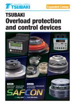
Expanded Lineup Overload protection and control devices Shock Guard Torque Limiter Axial Guard Shock Relay Torque Keeper MINI-KEEPER Shock Monitor Safety and Control devices
Open the catalog to page 1
Safety devi ces for pr otecting machinery from potentially damagi ng mechani cal and electrical overload. Both mechani cal and electrical types are available. From safety mechanisms like Torque Limiter, Shock Guard and Shock Relay, to controlling devices like Torque Keeper and Shock Monitor, SAFCON provides your vital machinery with top-notch safety and control. Contri buti ng to device automation.
Open the catalog to page 2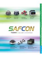
Shock Guard Friction type Separation type Linear actuating type Current type TGK Series TGZ Series TGM Series TGF Series TGX Series TGE Series TGB Series Shock Relay Axial Guard Shock Guard Axial Guard Torque Limiter Torque Limiter Shock Relay Shock Monitor Mechanical type slipping clutch and brake Mechanical type slipping clutch and brake Electric type overload protection device and load sensor Torque Keeper SA Series Shock Monitor MINI-KEEPER Torque Keeper TSUBAKI Safety and Control devices
Open the catalog to page 3
Variation Overload Protection Mechanical type What it detects Torque Thrust Load Motor current Disconnection (trip) method Ball type Friction type Display function Torque adjustment method Display method Spring pressure Air pressure Spring pressure Spring pressure Reset after trip Automatic/ Manual Digital display Standard functions Open Lower limit 下限検知 detection Construction Open Analog display Shock Guard Wide variety of sizes Shock Guard TGB Series Shock Guard TGX Series Shock Relay Axial Guard Torque Limiter Large capacity Select by motor capacity Shock Guard TGM Series Set torque 1.5 to...
Open the catalog to page 4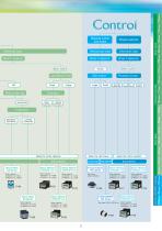
Electrical type Motor power Load detection level Reset after trip Slip torque Contact detection Wear detection Crusher control Limited functions Axial Guard Torque Limiter Motor power Shock Guard Mechanical type Limited functions Shock Relay Standard functions TGK Series TGZ Series TGM Series TGF Series TGX Series TGE Series TGB Series Electrical type Power sensor Slipping clutch and brake Shock Monitor ショ ックモニタ Shock Monitor ショ ックモニタ Shock Relay S Series A Shock Relay 50 Series Motor capacity : AC200V0.2 to 3.7kW AC400V0.2 to 3.7kW Torque Keeper トルクキーパー T K Series F Shock Monitor ショ ックモニタ Shock...
Open the catalog to page 5
SAFCON contributes to the protection and control Starting with the examples below, SAFCON meets a wide range of industrial equipment safety and control needs. Shock Guard TGB Series Category Protection, detection, applications Safety or Control Page Transport equipment Environmental equipment Packaging machine Food processing machine Machine tools Metal working machinery Iron and steel Plastic processing machine Textile machine Printing machine IT S Crane S Hoist S Chain block Overhead conveyor S Overhead conveyor S S Belt conveyor S Belt conveyor S Chain conveyor S Chain conveyor S Roller conveyor...
Open the catalog to page 6
ショックリレー Axial Guard Torque Limiter ミ ニキーパー トルクキーパー Shock Relay
Open the catalog to page 7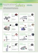
Providing optimal overload protection TSUBAKI mechanical and electrical safety devices provide overload protection for various applications. Packaging machine Cutter drive portion overload protection Rotary filling and packaging machine Product used Shock Guard TGB Series Protects the machine from intrusion Shock Guard TGE Series ●Automatic reset ●Automatic reset Protects the machine from paper jams ●Works with wide gears Index table Product used Shock Guard TGX Series Small precision printer Product used Indexer protection Product used Shock Guard TGF Series ●Non-backlash ●Automatic reset ●One...
Open the catalog to page 8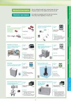
Shredder Temporarily stops the shredder when the load becomes heavy ● Loads on multiple conveyors can be monitored remotely with a PC using the communication function. ●Parameter values can also be changed remotely. Submersible pump Product used Shock Relay SA Series Prevents pump motor burnout Product used Shock Relay SU Series Overload protection and breakage detection for each tool ● Convenient automatic reset for frequent stops ●Compact Multi-spindle drilling machine ●Test functions Water treatment equipment Product used Sewage collector chain breakage prevention Product used Shock Monitor...
Open the catalog to page 9
Slipping clutch and brake Because it is possible to use even with continuous slipping, it is ideal for braking, accumulation and dragging. Multistory parking facility When the table strikes the stopper and stops, the Torque Keeper slips, protecting the drive portion. Wire winding machine Product used By installing a MINI-KEEPER to the roll, constant tension allows the wire to wind smoothly Torque Keeper TFK Series Product used MINI-KEEPER MK Series ●Stable slip torque ●Continuous slip is possible ●Long life ●Gives ideal amount of ●Simple layout tension for the work piece Power sensor Preventitive...
Open the catalog to page 10
Mechanical Type Shock Guard, Torque Limiter, Axial Guard Features, variation Selection guide Ordering method Torque Limiter Axial Guard
Open the catalog to page 11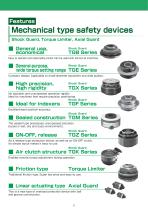
Mechanical type safety devices Shock Guard, Torque Limiter, Axial Guard Shock Guard Easy to operate and reasonably priced. Can be used with almost all machines. Shock Guard wide torque setting range TGE Series Compact design. Applicable to small-diameter sprockets and wide pulleys. ■ High precision, high rigidity Shock Guard No backlash and unsurpassed operation rigidity. Ideal for machines that require precision positioning. Shock Guard Excellentreset position accuracy. Shock Guard ■ Sealed construction TGM Series The sealed type possesses unsurpassed precision. Excels in wet, oily and dusty...
Open the catalog to page 12
Mechanical safety device variation In order to meet the diverse needs of our customers, we provide a wide range of mechanical safety products. Refer to the chart below to choose the functions and device characteristics that best suit your safety needs. Product name Shock Guard TGB Series Compact size (TGB08 to 16) Repetitive motion torque accuracy Reset method Overload detection Torque indicator Torque Limiter Axial Guard Function, capacity Product name Shock Guard Repetitive motion torque accuracy Reset method External force (manual) Overload detection Limit switch Limit switch Proximity switch,...
Open the catalog to page 13All Tsubakimoto Chain catalogs and technical brochures
 TSUBAKI DIRVE CHAINS & SPROCKETS
234 Pages
 TIMING beltand pulleys
72 Pages
 REDUCER FOR SERVO MOTORS TERVO
42 Pages
 TSUBAKI COUPLINGS
120 Pages
 Tsubaki Miter Gear Box
64 Pages
 Drive Chains & Sprockets
219 Pages
 Cam Clutch BR-HT Series
8 Pages
 Tsubaki Couplings
120 Pages
 Tsubaki Lambda Chain Leaflet
6 Pages
 Tsubaki Pin Gear Drive Units
6 Pages
 Tsubaki gear motors 40 W - 5.5 kW
268 Pages
 Titan Series Chain
4 Pages
 TRAXLINE Cables for Motion
88 Pages
 Power-Lock
88 Pages
 SJ3 Sealed Joint Technology
2 Pages
 TKA Series Plastic Cable Carrier
21 Pages
 Tsubaki Smart Tooth
2 Pages
 Tsubaki Cam Clutch Box Series
16 Pages
 Tsubaki Cam Clutch
92 Pages
 Tsubaki Pin Oven Chain
4 Pages
 Top Chain Engineering Manual
76 Pages
 Tsubaki Pin Gear Drive Units
16 Pages
 Tsubaki Cleanveyor
12 Pages
 Tsubaki Gripper Chain
6 Pages
 Tsubaki Top Chain
246 Pages
 Tsubaki Small Size Conveyor Chains
168 Pages
 Tsubaki Palm Oil Mill Chain
2 Pages
 Tsubaki PC Chain Brochure
12 Pages


Archived catalogs
 Tsubaki Custom Made Chain
90 Pages
 ZIP CHAIN ACTUATOR
56 Pages


- Cylinder
- Actuator
- Electric gearmotor
- Linear actuator
- Power transmission belt
- Articulated telesocpic boom lift
- Tsubaki conveyor belt
- Precision gearhead
- Hydraulic cylinder
- Tsubaki right angle gear reducer
- Compact gearhead
- Solid-shaft gearhead
- Hollow-shaft gearhead
- Flexible coupling
- Gear train gear reducer
- Tsubaki shaft coupling
- Protection relay
- Transmission gearhead
- Compact actuator