
- Catalogs
- Tsubakimoto Chain
- High-precision overload protection device using balls or cams.


- Company
- Products
- Catalogs
- News & Trends
- Exhibitions
High-precision overload protection device using balls or cams.

High-precision overload protection device using balls or cams.
TSUBAKI provides a range of overload protection and control devices to protect machinery from mechanical and electrical overloads, enhancing automation and safety in industrial equipment.
- Torque Limiter: Friction type that slips at a preset torque to prevent overload.
- Shock Guard: Available in various series for different applications, offering separation and linear actuating types.
- Axial Guard: Provides axial direction overload protection.
- Shock Relay: Monitors motor current with digital display options for overload protection.
- Shock Monitor: Electric overload protection device with load sensors.
- Torque Keeper and MINI-KEEPER: Mechanical slipping clutches and brakes for stable slip torque and tension control.
- Torque settings range from 0.294 to 9310Nm, with varying maximum RPMs.
- Features include automatic reset, non-backlash, and remote torque adjustment.
- Shock Relays offer motor capacity selection, display functions, and remote monitoring.
- Used in industries like transport, environmental equipment, packaging, and more.
- Protects machinery from overloads, jamming, and breakages.
TSUBAKI's devices are essential for protecting industrial machinery from overloads, enhancing automation and operational efficiency.
- Self-Holding Circuit: Recommended for optimal performance.
- Axis Installation: Use specified shaft diameter tolerance and key. Tighten bolts and use Loctite 242 to prevent loosening.
- Drive Member Installation: Use 3 mounting seats and specified torque. Consult TEM for Power Lock combinations.
- Details for models TGM3 to TGM800 with movement and force specifications.
- Installation Bolts: Follow recommended screw-in lengths and torque values.
- Resetting: Stop rotation, remove overload causes, reset with input rpm below 50r/min.
- Pre-packed with high-quality grease; regular greasing not necessary under normal conditions.
- Connections between variators, reducers, or intermittent drive devices. Torque adjusted using the adjustment nut.
- Overload protection and ON-OFF clutch functionality with easy torque adjustment.
- Ensure proper assembly and disassembly. Regular maintenance includes greasing annually or every thousand trips.
Ensure adjustment nut or bolt is not turned beyond the torque indicator's maximum value to avoid locking the mechanism.
Non-backlash and complete release type, suitable for high-speed applications up to 1800 r/min.
The TGK series features an air clutch ON-OFF mechanism for remote torque adjustment by regulating air pressure.
Transfers driving force via drive balls, with torque adjustable during operation by changing air pressure.
Specifications for models TGK20-A2, TGK30-A2, and TGK45-A2, including torque ranges and air pressure requirements.
Torque adjusted by air pressure, with a range of 0.14 to 0.55 MPa, allowing for torque changes during operation.
Includes components like air filters, regulators, and solenoid valves for simple torque adjustments.
- Low Power Voltage: Caution advised when using voltage-operated loads like relays.
- Small Load Current: Connect a breeder resistance in parallel with the load to ensure the load current exceeds 5mA.
- Large Inrush Current Loads: Use a relay to prevent deterioration or damage to the opening and closing elements.
- Overcurrent Detection: Instantly detects overcurrent and outputs a relay contact signal after a preset time.
- Installation: Easy to install on existing equipment without major modifications.
- Abnormal Signal Output: Only outputs an abnormal signal under sustained overcurrent conditions.
- ED Series: Used in lifting devices for illumination and screens.
- SS Series: Protects chip conveyors from damage.
- SC Series: Used in mixers to adjust speed based on load changes.
- SU Series: Prevents pump motor burnout due to water shortage.
- Provides specifications for various Shock Relay series.
- Considerations for selecting Shock Relays based on motor capacity, voltage, and operation power source.
- Details on special models with features like impact load detection.
- Output: 4 to 20mA for load analysis and recording.
- Mounting: Available in panel type with detachable display.
- Detection: Undercurrent detection and maintenance indicators included.
- Compliance: CE marking and RoHS conformity.
- Overcurrent Settings: Adjustable based on the number of wires passing through the CT hole.
- Start and Shock Time: Configurable start time and shock time.
- Phase Reversal and Loss: Trips within specified times to prevent damage.
- Rated Load: 3A, 250VAC.
- Life Expectancy: 100,000 activations at rated load.
- Temperature: Operates between -20 to +60°C.
- Humidity: 30 to 85% RH without condensation.
- Buttons: ESC, UP/DN, and SET buttons for parameter adjustments.
- LED Display: Shows phase, unit, load ratio, and operational data.
- RS485/Modbus: Enables central monitoring and data logging.
- 4 to 20mA Output: Used for remote monitoring and control applications.
- Parameter Selection: Adjustable via UP/DN and SET buttons.
1. Imbalance Threshold: Set between 10% to 50% to detect current imbalance.
1. Stall Threshold: Set the ratio against overcurrent setting for detecting lock during start.
1. Analog Output Range: Set current value for 20mA output.
1. Reset Options: Self-holding or automatic reset options available.
1. Overcurrent, Phase Loss, Phase Reversal, Stall, Jam, Imbalance, Under Current, and Auto-reset Limitation are detailed with solutions for each trip condition.
1. Guidelines for the number of motor wires through CT based on load ratio and motor specifications.
1. RS-485 communication standards with a maximum distance of 1200m.
1. Displays motor current and settings digitally, includes CT in a compact unit, and is compatible with inverters.
1. Detailed descriptions of LED display, current setting, start time, shock time, DIP switch, test button, and reset button functions.
- Start Time Function: Allows the Shock Relay to ignore motor starting current within a set time.
- Shock Time Function: Delays the relay's response to excess current.
- Design: Compact with integrated current transformer (CT).
- Motor Capacity: Supports motors from 0.2kW to 90kW.
- Control Power Supply Voltage: Available for AC100V to 240V systems.
- Overload Mode: The relay trips when the motor current exceeds the set value.
- Basic Connection Diagram: Provides guidance on wiring and installation.
- Special Models: Available for specific requirements such as UL/cUL and CCC standards compliance.
- Test and Reset Functions: The Shock Relay includes test and reset buttons for operational checks.
- Shock Time: Adjustable between 0.2 to 5 seconds.
- Start Time: Ranges from 0.2 to 10 seconds.
- Test and Reset Functions: The Shock Relay can be tested independently or during motor operation.
- CT Wiring: The current transformer (CT) is pre-wired at the factory.
- TSBSS Series: Includes models like TSBSS05, TSBSS30, and TSBSS60.
- Ensure transformers are set according to the voltage of the Shock Relay and magnetic contactor.
The document outlines the specifications and features of various Shock Relays and Torque Keepers.
The Shock Relay operates by monitoring the motor current and tripping if the current falls below a set level.
For optimal performance, ensure the correct number of wires pass through the CT hole based on motor load factors.
The document includes basic connection diagrams for the Shock Relay and Torque Keeper.
The Shock Relay's setting current range varies by model.
- Specifications: The MINI-KEEPER models have varying torque ranges and masses.
- Features: Designed for monitoring light loads, the Shock Monitor is unaffected by voltage fluctuations.
- Install suitable protection devices when using with human transport or lifting devices.
The document provides technical specifications and operational guidelines for the Shock Monitor.
- Communication: Utilizes RS485, half-duplex, bidirectional Modbus protocol.
- Real-time monitoring of power and current waveforms for preventive maintenance.
- Includes a touch panel display, LED indicators, and various connectors.
- Parameters include motor voltage, motor kW, start time, and process levels.
- Basic Type: Used for general industrial machines.
- Ability to detect minute load changes and provide alarm signals.
Specifications for various motor capacities and voltage classes.
Instructions for setting parameters like inhibit time and auto inhibit function.
Describes the function of various terminals.
Safety guidelines emphasize verifying no load or rotational force before maintenance.
Warranty covers 18 months from shipment or 12 months from first use.
Recommendations include using relays for minute electric currents.
- If the instruction manual is unavailable, request one from the distributor or sales office.
Catalog excerpts

Expanded Lineup Overload protection and control devices Shock Guard Torque Limiter Axial Guard Shock Relay Torque Keeper MINI-KEEPER Shock Monitor Safety and Control devices
Open the catalog to page 1
Safety devices for protecting machinery from potentially damaging mechanical and electrical overload. Both mechanical and electrical types are available. Creating device safety and control From safety mechanisms like Torque Limiter, Shock Guard and Shock Relay, to controlling devices like Torque Keeper and Shock Monitor, SAFCON provides your vital machinery with top-notch safety and control.
Open the catalog to page 2
Torque Limiter Friction type Shock Guard Separation type Axial Guard Linear actuating type Shock Relay Current type TSUBAKI Safety and Control devices Mechanical type slipping Mechanical type slipping Shock Monitor Electric type overload protection device and load sensor
Open the catalog to page 3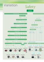
Mechanical type ["Torque) ^Thrust Load) Shock Relay Motor capacity: Shock Relay Shock Relay Motor capacity: Shock Relay Mqtqr qapaqity: Mqtqr qapaqity:
Open the catalog to page 4
Electrical type ^Motor powerj Load detection level Reset after trip Select by motor capacity Shock Monitor Motor capacity: Motor capacity: Shock Relay Shock Monitor Motor capacity: Shock Monitor Motor capacity: Motor capacity: Slipping clutch Power sensor Mechanical type I Electrical type What it detects What it detects Slip torque ^Motor powerj f Large 1 f Small ] f Contact ] f Wear ] detection^ ^detection [ Select by slip torque ] [ Select by motor capacity J Torque Keeper I MINI-KEEPER Shock Monitor Torque Keeper Shock Monitor Motor capacity: Shock Monitor Motor capacity: Shock Monitor Set...
Open the catalog to page 5
Starting with the examples below, SAFCC ts a wide range of industrial equipment safety and control needs. Shock Guard Series Series Series Series Series Series Series Metal working Chain block Belt conveyor Belt conveyor Garbage disposal equipment S Water treatment equipment S Water gate Bag making and packaging machine S Vacuum packaging machine S Injection molding machine S Gear pump for extruding machine S Textile weaving loom C Book binder Liquid crystal manufacturing device S Semiconductor production device S Automotive testing machine S Stage device Overload protection for machine overload,...
Open the catalog to page 6
®:Optimal •: Recommended Shock Relay Torque MINI- Keeper KEEPER Shock Monitor Series Series Type HI Type H2 Type
Open the catalog to page 7
TSUBAKI mechanical and electrical safety devices provide overload protection for various applications. Providing optimal overload protection Packaging machine Cutter drive portion overload protection Shock Guard Automatic reset Small precision printer from paper jams Shock Guard Automatic reset Rotary filling and packaging machine I pr0Ciuct Protects the machine from intrusion I used I Index table Indexer protection Automatic reset Works with wide gears Shock Guard Automatic reset from highly viscous material Shock Guard Sealed construction Works when closing a cap with the prescribed torque...
Open the catalog to page 8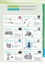
Mechanical type features Due to cutting the peak load, overload does not occur. Excessive power to the loaded axis can be shut off. Electronic type features All models are equipped with the start time function. Price stays same regardless of motor size. Protects the mechanical system from overload due to the work piece getting Axial Guard •Can protect from overload Lifting and lowering device Detects overweight Shock Relay • While verifying motor current during operation, the load value can be precisely Multiple conveyors Perform remote monitoring by Shock Relay Stops overload when spoons or...
Open the catalog to page 9
Application Contm Slipping clutch and brake Because it is possible to use even with continuous slipping, it is ideal for braking, accumulation and dragging. Multistory parking facility When the table strikes the stopper and stops, the Torque Keeper slips, protecting the drive portion. Torque Keeper •Stable slip torque •Long life •Simple layout Wire winding machine the roll, constant tension allows the wire to wind smoothly •Continuous slip is possible •Gives ideal amount of tension for the work piece Power sensor Preventitive device maintenance and automation can be realised by detecting minute...
Open the catalog to page 10
Shock Guard, Torque Limiter, Axial Guard Shock Guard TGB Series p21 to p34 ® Shock Guard TGE Series p35 to p40 |^ shock Guard TGX Series p41 to p50 shock Guard TGF Series p51 to p62 Shock Guard TGM Series p63 to p70 Shock Guard TGZ Series p71 to p78 Shock Guard TGK Series p79 to p86
Open the catalog to page 11
Mechanical type safety devices Shock Guard, Torque Limiter, Axial Guard Shock Guard Easy to operate and reasonably priced. Can be used with almost all machines. ■ General-purpose, shock Guard wide torque setting range TGE Series Compact design. Applicable to small-diameter sprockets and wide pulleys High precision, high rigidity Shock Guard No backlash and unsurpassed operation rigidity. Ideal for machines that require precision positioning. Shock Guard M Ideal for indexers TGF Seri Excellentreset position accuracy. Shock Guard M Sealed construction TGM Series The sealed type possesses unsurpassed...
Open the catalog to page 12
Mechanical safety device variation In order to meet the diverse needs of our customers, we provide a wide range of mechanical safety products. Refer to the chart below to choose the functions and device characteristics that best suit your safety needs. Shock Guard Compact size Medium size Large size With sprocket Torque range Repetitive motion torque accuracy Reset method Torque indicator Shock Guard Torque Limiter Axial Guard Torque range (Load range[N]) Repetitive motion torque accuracy (trip load) Reset method External force Limit switch Limit switch Proximity switch, Torque indicator *1 Only...
Open the catalog to page 13
The right mechanical type safety device for your particular needs is available. Using the chart below, select the device that is most right for your machines. For machinery like positioning and indexing machines that require Repetitive motion torque accuracy This represents the deviation caused by repeated
Open the catalog to page 14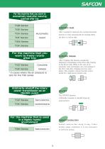
For the machine that you want to automatically reset after removing nvprlnari after trin Arbitrarily transmit or shutoff torque by external force. For the machine that is used Sealed construction Sealed Construction Sealed construction using O-ring. Under normal usage conditions it is not necessary
Open the catalog to page 15All Tsubakimoto Chain catalogs and technical brochures
 TSUBAKI DIRVE CHAINS & SPROCKETS
234 Pages
 TIMING beltand pulleys
72 Pages
 REDUCER FOR SERVO MOTORS TERVO
42 Pages
 TSUBAKI COUPLINGS
120 Pages
 Tsubaki Miter Gear Box
64 Pages
 Drive Chains & Sprockets
219 Pages
 Cam Clutch BR-HT Series
8 Pages
 Tsubaki Couplings
120 Pages
 Tsubaki Lambda Chain Leaflet
6 Pages
 Tsubaki Pin Gear Drive Units
6 Pages
 Tsubaki gear motors 40 W - 5.5 kW
268 Pages
 Titan Series Chain
4 Pages
 TRAXLINE Cables for Motion
88 Pages
 Power-Lock
88 Pages
 SJ3 Sealed Joint Technology
2 Pages
 TKA Series Plastic Cable Carrier
21 Pages
 Tsubaki Smart Tooth
2 Pages
 Tsubaki Cam Clutch Box Series
16 Pages
 Tsubaki Cam Clutch
92 Pages
 Tsubaki Pin Oven Chain
4 Pages
 Top Chain Engineering Manual
76 Pages
 Tsubaki Pin Gear Drive Units
16 Pages
 Tsubaki Cleanveyor
12 Pages
 Tsubaki Gripper Chain
6 Pages
 Tsubaki Top Chain
246 Pages
 Tsubaki Small Size Conveyor Chains
168 Pages
 Tsubaki Palm Oil Mill Chain
2 Pages
 Tsubaki PC Chain Brochure
12 Pages


Archived catalogs
 Tsubaki Custom Made Chain
90 Pages
 ZIP CHAIN ACTUATOR
56 Pages


- Cylinder
- Actuator
- Electric gearmotor
- Linear actuator
- Power transmission belt
- Articulated telesocpic boom lift
- Tsubaki conveyor belt
- Precision gearhead
- Hydraulic cylinder
- Tsubaki right angle gear reducer
- Compact gearhead
- Solid-shaft gearhead
- Flexible coupling
- Hollow-shaft gearhead
- Tsubaki shaft coupling
- Gear train gear reducer
- Protection relay
- Transmission gearhead
- Compact actuator