
- Catalogs
- Tsubakimoto Chain
- Drive Chains & Sprockets


- Company
- Products
- Catalogs
- News & Trends
- Exhibitions
Drive Chains & Sprockets

Drive Chains & Sprockets
Leonardo da Vinci is credited with the initial concept of the roller chain, which has evolved into the modern drive chain. His ideas are documented in his notebooks, and a portrait made of link plates is displayed at Tsubakimoto Chain’s Kyotanabe Plant.
The Tsubaki Chain Group prioritizes global environmental protection through policies aimed at reducing environmental impact, improving management systems, complying with regulations, and educating the workforce. The Kyotanabe Plant is equipped with advanced systems to produce environmentally friendly products.
Tsubakimoto Chain has received ISO9001 accreditation in 1995 and ISO14001 in 2003, reflecting their commitment to quality and environmental management.
The document details various roller chain products, including RS Roller Chains, Lambda Chains, and Super Roller Chains, each designed for specific applications and environments. The G8 Series offers improved wear life and corrosion resistance.
Guidelines for handling roller chains include cutting, connecting, lubrication, installation, and inspection. Special precautions are advised for use in unique environments.
Selection guides and safety precautions are provided to ensure proper use and maintenance of chains and sprockets, minimizing the risk of accidents.
A range of accessories, including chain tensioners, idler sprockets, and lubricators, are available to support chain maintenance needs.
Tsubaki offers a comprehensive line-up of drive chains and sprockets designed to enhance productivity and meet diverse operational requirements.
The document outlines the specifications for roller chains, including the moment of inertia, total length tolerance, and elastic elongation under load. The length tolerance is specified according to JIS B 1801:2014, with a tolerance of 0 to +0.15% of the reference length for RS 80 chains.
The basic structure of roller chains includes plates, pins, bushes, and rollers. Each component has specific requirements for strength and resistance to wear and shock. The document details the dimensions and fitting types, such as slip fit and press fit, for assembling the chains.
The document categorizes roller chains into standard, lube-free, heavy-duty, corrosion-resistant, and specialty chains. Each type has specific features, such as high tensile strength or corrosion resistance, and is suitable for different operating conditions and applications.
The recommended lubrication systems and lubricants are specified for different chain types. Proper lubrication is crucial for maintaining chain performance and longevity, especially under varying temperature conditions.
Guidelines for ordering specific chain lengths and types are provided, including the use of connecting and offset links. The document emphasizes the importance of using the correct assembly parts and methods to ensure chain integrity and performance.
The document includes kilowatt ratings tables and operating temperature ranges for different chain types. These tables help in selecting the appropriate chain for specific applications based on load and environmental conditions.
- RS Roller Chain: Standard chain with basic dimensions.
- Super Chain: Offers a 40% increase in maximum allowable load over RS Roller Chain, suitable for fatigue-prone applications.
- RS-HT Chain: 20% greater tensile strength than RS Roller Chain, ideal for high tensile strength applications.
- Super-H Chain: Higher allowable load and fatigue strength, designed for shock absorption.
- Ultra Super Chain: Highest allowable load, tensile strength, and shock absorption, suitable for compact drives.
- Use RS Roller Chain for high-speed applications not covered in the kW ratings table.
- Offset links are not available; use an even number of links.
- Both single and multi-strand chains can use RS sprockets, but multi-strand RS-HT and Super-H chains cannot.
- Small sprockets must have heat-treated hardened teeth and be made of S35C or higher carbon steel.
- Connecting links use ring coining for easy attachment and removal while maintaining strength.
- Four-pitch offset links (4POL) are available for single strand chains only, with a maximum allowable load of 85% of the base chain.
- High kW ratings and shock absorption capabilities.
- Users can opt for smaller chain sizes compared to RS Roller Chain.
- TOUGH TOOTH sprockets are optimized for use with Heavy Duty Drive Chain.
The document provides detailed specifications for sprockets, including nominal dimensions that may differ from actual dimensions. Items marked with an asterisk (*) have a groove on the hub perimeter to prevent sprocket-chain interference. Various models are available, including RS Sprockets in both steel and stainless steel, with options for single and double strands.
Models are available for easy bore finishing, with a wide range of stocked bore finishing specifications. Customers can select hub models, number of teeth, tooth hardening, surface treatment, bore diameter, bore tolerance, keyway tolerance, and tap hole processing.
Surface treatments include black oxide treatment, electroless nickel-phosphorous plating, and electrogalvanized trivalent chromate. Black oxide treatment may require additional finishing, while the other two do not.
The document outlines bore finishing and keyway specifications, including bore diameter, keyway width, and tap size. Tolerances are selectable, and keyway dimensions follow JIS standards. Bore chamfering dimensions are provided, with options for different bore diameters.
Lock Sprockets are keyless friction type integrated coupling sprockets available in models RS35 to RS100 1B Type. They feature a tightening principle and specific bolt tightening positions. The document advises on allowable transmission torque, shaft diameter tolerance, and surface roughness.
When mounting Lock Series S Type sprockets, consider the movement of the sprocket during tightening. Ensure the load torque does not exceed specified limits, and use a torque wrench for bolt tightening. The operating temperature range is -20℃ to 200℃.
The Lock Series is designed for secure mounting of sprockets on shafts. Key features include no wobbling after mounting, easy phase alignment, and simple mounting and dismounting without the need for retainers. The system uses a tapered inner diameter on the sprocket and a tapered outer diameter on the lock sleeve. Tightening the mounting bolts causes the sprocket to slide up the tapered surface, creating a wedge action that generates radial forces to secure the sprocket tightly to the shaft.
The document provides detailed specifications for various models within the RS35, RS40, and RS50 Lock Series. Each model is identified by a specific configuration and number of teeth, with options for hardened or non-hardened teeth. The sprockets are compatible with specific chain pitches and roller diameters, and the document includes tables listing dimensions, bolt sizes, and tightening torques for each model.
Models are available in configurations A and B, with specific notes on compatibility to avoid interference with chains. The document emphasizes checking the installation guide before attaching mounting bolts and provides detailed instructions for inputting bore diameters and selecting configurations.
Tables in the document list the dimensions for each model, including pitch circle diameter, hub diameter, and applicable bore diameters. Maximum allowable torque values are provided for each model, ensuring users can select the appropriate sprocket for their application needs.
1. Input bore diameter and configuration in specified boxes.
2. Dimensions are nominal and may differ from actual measurements.
3. Models with asterisks indicate limited configuration availability.
The document provides detailed technical specifications and installation procedures for various types of idler sprockets and chain tensioners used in roller chains. It covers different models, their construction, assembly, and installation guidelines, as well as ordering information.
The idler sprockets are equipped with built-in bearings and are available in different types: TCS, ETS, TH, and TA. Each type has specific features such as induction-hardened teeth and different coatings or platings. The document includes tables listing model numbers, sprocket sizes, bolt specifications, and tightening torques.
The idler sprockets are constructed with a main unit, coil spring, and various bolts and washers. The TCS and ETS types require assembly with specific washers and bolts, while the TA type comes pre-assembled with a plastic shoe. Detailed assembly instructions are provided, including diagrams for clarity.
Installation involves securing the idler sprocket and tensioner with bolts, ensuring proper alignment with the chain. The document emphasizes the importance of using bolts with a strength classification of 8.8T or more and provides torque specifications. It also includes step-by-step instructions for attaching different types of tensioners, with diagrams illustrating the correct positioning and alignment.
The document outlines the ordering process, including model numbers, quantities, and applicable chain types. It specifies operating temperature ranges and provides examples of how to order different models.
- Ensure proper alignment of the idler sprocket and chain to prevent vibration and noise.
- Regularly lubricate the rod section of the tensioners.
- Use spacers as indicated to prevent contact between the tensioner and roller chain.
This document serves as a comprehensive guide for selecting, assembling, and installing idler sprockets and chain tensioners, ensuring optimal performance and longevity of roller chain systems.
- Various chain tensions are specified for different conditions such as deceleration, shuttle drive, load side torque, prime mover output, starting torque, braking torque, and acceleration. Each condition has both actual and design tension values expressed in kN and kgf.
- Coefficient of friction between roller and rail is given with and without lubrication. Standard gravity acceleration is noted. Speed ratio and moment of inertia are defined. Several factors such as shock, number of teeth, service, RPM, imbalance load, and speed are referenced to specific tables.
- Details include number of teeth for large and small sprockets, chain pitch, attachment height, and various torques (maximum, braking, starting, load, working, and rated). Chain speed and length, unit mass, and RPM for different components are specified.
- Various formulas are provided for calculating chain tensions, acceleration and deceleration times, and other parameters. These include considerations for transmission efficiency and adjustments for multi-strand chains.
- A step-by-step method for selecting roller chains is outlined, including checking required information, calculating design kW, determining chain length, and deciding on lubrication methods. Specific steps are provided for selecting chain and sprocket sizes based on speed ratios and space limitations.
- The document describes methods for general selection and allowable load selection, emphasizing the importance of service factors, design chain tension, and checking motor characteristics. It includes procedures for calculating chain tension during acceleration and deceleration and selecting appropriate chain sizes.
1. For transmissions experiencing large shocks or extreme conditions, such as large-load transmissions or those with thrust loads, use F-type connecting links or two-pitch offset links.
2. When using one-pitch offset links or Super Chain 4 pitch offset links, allowances for strength should be made with respect to the maximum allowable load:
- M-type CL: 100%
- F-type CL: 100%
- Two-pitch offset link: 100%
- One-pitch offset link: 65%
- 4 pitch offset link: 85%
- Super Chain single strand: 60%
- BS/DIN Chain: 60%
4. For high-speed sprockets, use sprockets with hardened tooth tips.
5. Ensure roller chains are lubricated due to high bearing pressure. Allow an 80% reduction for M type connecting links for specific corrosion-resistant roller chains.
1. The selection method uses maximum allowable load for products without kilowatt ratings or those operated at low speeds with frequent stops.
2. Calculations for rated torque, starting torque, maximum torque, and braking torque are provided, with specific formulas and examples.
3. Chain tension calculations are detailed, considering factors like conveyor roller rotation torque, sprocket dimensions, and usage factors.
4. Tentative chain selections are made based on calculated tensions and maximum allowable loads, with examples provided for different scenarios.
5. Lubrication recommendations are given for different chain types, emphasizing the use of oil baths or slinger discs.
1. The document provides detailed steps for calculating chain tension during acceleration and deceleration, considering factors like inertia and shock.
2. Recommendations for sprocket and chain combinations are given, with specific attention to sprocket bore diameters and shaft diameters.
3. The importance of selecting appropriate chain sizes and lubrication methods based on operational conditions is emphasized.
The document provides detailed calculations for working torque, inertia ratio, and chain tension during acceleration and deceleration. It includes formulas for calculating motor braking torque and chain tension, emphasizing the importance of these parameters in the design and selection of roller chains.
Step-by-step procedures are outlined for calculating acceleration and deceleration times, as well as the inertia ratio. The document also details the process for selecting the appropriate roller chain based on these calculations.
The document references specific standards for roller chain selection, including the maximum allowable load and the impact of temperature on chain performance. It advises on the selection of corrosion-resistant chains and the importance of considering ambient conditions.
There is a section dedicated to the effects of temperature on roller chain performance, including the degradation of strength at high temperatures and the brittleness at low temperatures. Recommendations for lubrication and adjustments in high-temperature environments are provided.
A guide is included for assessing the corrosion resistance of chains and sprockets under various chemical exposures. This section emphasizes the need to verify corrosion resistance based on actual operating conditions.
The document provides instructions for cutting roller chains to the necessary length, including the use of a chain vise and punch. It highlights the importance of proper handling to avoid damage to the chain components.
The document concludes with a summary of the selected chain and sprocket specifications, emphasizing the need for careful consideration of environmental conditions and the importance of adhering to the outlined procedures and standards.
When grinding the riveted portion of a rivet-type pin, use a grinder to avoid damage and extra effort. Do not reuse removed parts.
- Using a Chain Breaker: Grind down one end of the outer plate's pins before removing them. Ensure the bush is not loose or deformed.
- Cutting Poly Steel Chain: Support the chain in a cradle and use an exclusive punch. Avoid excessive force on plastic parts.
- Cutting Lambda Chain: Use a chain vise and grind pins carefully to avoid overheating. Use an exclusive cradle and punch for cutting.
- On Sprocket Teeth: Wind the chain around the sprocket, insert the connecting link, and secure it with clips or pins. Avoid damaging sprocket teeth.
- Between Shafts: Use a chain puller to bring chain ends together, insert the connecting link, and secure it.
- Clip and Cotter Pins: Ensure clips are securely inserted and cotter pins are bent properly. Do not reuse cotter pins.
Proper lubrication is crucial to prevent wear and corrosion. Apply lubricant to the gaps between plates and bushes. Avoid removing the factory-applied lube. For outdoor use, protect chains from rain and snow.
- Speed Ratio and Chain Wrap: Maintain a speed ratio up to 7:1 and ensure chain wrap is at least 120°.
- Distance Between Shafts: Optimal distance is 30-50 times the chain pitch. Adjust slack to 4% of the span.
- Horizontal Precision and Parallelism: Ensure sprockets are installed with precision to avoid chain and sprocket damage.
1. Sprocket Alignment: Use a straightedge to ensure sprockets are parallel, adjusting within specified values based on shaft distance.
2. Chain Layout: Maintain a level line connecting sprocket centers. Use idlers or tensioners for vertical layouts to prevent chain stretch and disengagement.
3. Lambda Curved Chain Installation: Install a guide for proper sprocket engagement and ensure the minimum lateral bending radius meets specifications.
1. Sprocket Installation: Secure sprockets with appropriate locking mechanisms. Harden teeth under specific conditions to prevent wear.
2. Chain Test Run: Conduct pre-test checks for correct installation, lubrication, and absence of obstructions. During the test run, ensure smooth operation without unusual noises or vibrations.
1. Regular Inspections: Conduct monthly inspections, more frequently in harsh environments or high-speed operations.
2. Inspection Checklist: Check for lubrication, wear, and damage on chains and sprockets. Replace chains showing significant wear or damage.
3. Wear and Fatigue Checks: Inspect link plates, pins, and rollers for cracks or excessive wear. Adjust chain or guides if wear is detected.
1. Use of Guides and Tensioners: Employ guide shoes and tensioners to prevent vibration and maintain chain tension.
2. Proper Sprocket Engagement: Ensure uniform contact area on sprocket teeth to avoid improper installation effects.
1. Chain Wear Limit: Replace chains at 1.5% wear elongation.
2. Sprocket Tooth Wear: Replace sprockets when wear reaches specified limits or hardened layers are removed.
When a new roller chain is used on a worn sprocket, it accelerates chain wear. It is recommended to replace both the chain and sprocket simultaneously to ensure longevity.
Chain elongation results from wear on the pin and bush, not deformation of the link plate. Regular measurement of chain elongation helps estimate remaining chain life. Use a vernier caliper to measure the inside (L1) and outside (L2) of the rollers over 6 to 10 links to minimize error. The formula for chain elongation is: Chain elongation (%) = (Measured length - Standard length) / Standard length. The standard length is calculated as Chain pitch x Number of links.
For smooth transmission, the allowable chain elongation varies with sprocket size: up to 60 teeth (1.5%), 61-80 teeth (1.2%), 81-100 teeth (1.0%), and 101-110 teeth (0.8%).
Inspect for twisting and side bending. Replace the chain if these are observed. Check lubrication at connecting parts and around sprockets. Damaged end fittings should be replaced immediately.
Store roller chains in cool, dry environments. Clean and lubricate chains before storage, wrapping them in grease paper.
In wet conditions, improper lubrication increases wear. Use corrosion-resistant chains to prevent rust. In acidic or alkaline environments, chains may suffer embrittlement and corrosion. Protective casings and high-grade materials are recommended.
Common issues include chain riding up on sprockets, unusual noises, excessive vibrations, and improper lubrication. Remedies involve correct installation, proper lubrication, and replacing worn components. For link plate and pin-related issues, reducing shock loads and ensuring proper installation are key.
Catalog excerpts

TSUBAKI DRIVE CHAINS & SPROCKETS
Open the catalog to page 1
Leonardo da Vinci, founder of the roller chain (1452-1519) Leonardo da Vinci, the genius of the Renaissance, devised the prototype of a roller chain that today is widely used as a drive chain. His foresight and advanced ideas are revealed in his notebooks, which contain sketches of an object that looks remarkably like a modern chain. The photo shows a portrait of da Vinci, made entirely out of link plates, on display in the main lobby of Tsubakimoto Chain’s Kyotanabe Plant.
Open the catalog to page 2
The Start of a New EraBasic Environmental Policy of the Tsubaki Chain GroupPhilosophy The Tsubaki Chain Group recognizes that the protection of the global environment is one of the chief responsibilities of all mankind. It is our goal to show consideration for the environment in all of our business activities in order to contribute to a better tomorrow. ■ Always be aware of the environmental effects of business activities, products and services, and strive to reduce the related environmental load from the perspective of global environmental protection. ■ Streamline our organization for environmental...
Open the catalog to page 3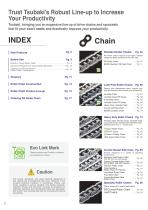
Trust Tsubaki’s Robust Line-up to Increase Your Productivity Tsubaki, bringing you an expansive line-up of drive chains and sprockets that fit your exact needs and drastically improve your productivity. Notes on Using Roller Chain …………………………………… Pg. 9 General Comparison of Transmission Elements ……………… Pg. 10 Features and Precautions of …………………………………… Pg. 10 Roller Chain Transmission Roller Chain Product Line-up Ordering RS Roller Chain RS Roller Chains feature even higher kilowatt ratings and better performance for each size. ……Pg. 22 RS Roller Chain BS/DIN Standard RS Roller Chain ……Pg. 51 Roller...
Open the catalog to page 4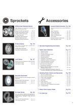
RS Sprocket Standard Series Accessories (Peripheral Instruments) Pg. 158 Wide se selection of standardized sprockets for general use RS Roller Chain. u Peripheral instruments for your chain maintenance ne eeds. Standard Pilot Bore Type Sprockets RS Sprocket Selection Guide TOUGH TOOTH Sprockets 2A Type Sprockets Single Dual Type Sprockets Stainless Steel Sprockets Engineering Plastic Sprockets Lock Series Keyless friction type integrated coupling sprockets s Lock Series S Type S Lock Series N Type S Eac model is provided with a finished bore, ch key yway, and set screws. Finished Bore Sprockets...
Open the catalog to page 5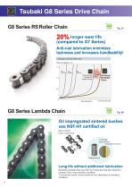
Tsubaki G8 Series Drive Chain G8 Series RS Roller Chain 20% longer wear life (compared to G7 Series) Anti-rust lubrication minimizes tackiness and increases handleability! Evolution of Chain Wear Life Wear elongation (%) 1.5 60 Series Previous G7 7 Series RS S Roller Chain longer G8 Series life Running time *In-house test data G8 Series Lambda Chain Oil impregnated sintered bushes use NSF-H1 certified oil Basic Lambda Chain construction (Us (Uses NSF-H1 food grade lubricant) Sintered bush Long life without additional lubrication G8 Series Lambda Chain can offer up to twice the wear life of...
Open the catalog to page 6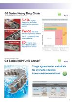
G8 Series Heavy Duty Chain Super Chain/RS-HT Chain/Super-H Chain Super Chain RS-HT Chain Comparison of min. tensile strengths and max. allowable loads maximum allowable load than the previous series! Ultra Super Chain RS-HT Chain life of the previous series! Minimum Tensile Strength Slip fit connecting links now available! Super-H Chain Super-H Chain allowable load than the previous series! Super Chain Maximum Allowable Load Note : With RS Roller Chain mim. tensile strength and max. allowable load as benchmark (100). Super Chain Super-H Chain RS-HT Chain Previous Super Chain Previous Super Chain...
Open the catalog to page 7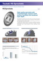
Tsubaki RS Sprockets RS Sprockets are perfect for G8 Series RS Roller Chain! High quality sprockets with overwhelmingly superior tooth surface hardness and hardened layer depth Sprockets for general use drive chain are strong enough to handle the chain, while the wear resistance of the teeth is as important as the chain itself. Tsubaki offers standard pilot bore type sprockets as well as standardized Strong Series sprockets, TOUGH TOOTH Sprockets, and a wide variety of other hardened tooth sprockets. Comparison of tooth hardening Comparison of tooth hardness and hardened layer depth Cross-sectional...
Open the catalog to page 8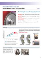
Recommended for Heavy Duty Drive Chain RS TOUGH TOOTH Sprockets A stronger, more durable sprocket Durable Teeth use induction hardened carbon steel Strong Welded hub uses new material that is 43% stronger Wear resistant Optional special surface coating available TOUGH TOOTH sprockets have increased strength and durability to bring out the best in Tsubaki’s G8 Series Heavy Duty Drive Chains. Stronger hubs Comparison of hub kW ratings (ex. using RS80-SUP-H-1) Torque 4000 3500 Space and cost savings! Example of fracture due to insufficient hub strength Extended hubs and other specialty specifications...
Open the catalog to page 9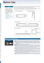
Before Use Standard Roller Chains Lube-Free Roller Chains Heavy Duty Roller Chains Corrosion Resistant Roller Chains Specialty Roller Chains Sprockets Pin Gear Drives Accessories Selection Handling Before Use NOTE With the exception of endless chains, the transmission power tables in this catalog are based on use with connecting parts (connecting links or offset links). See page 16 for details on connecting parts. The dimensions shown in this catalog are nominal dimensions and differ from actual dimensions. This drive chain catalog explains how to select, install and maintain all listed Tsubaki...
Open the catalog to page 10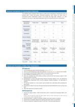
The following table compares roller chains to other power transmission mechanisms such as toothed belts, V-belts and gears. Generally speaking, roller chains are often used in economical power transmission suited to low speed and high loads. However, it is also possible to use chain in high-speed applications such as camshaft drives for automobiles. Transmission Mechanism ©Excellent OGood AFair xPoor Features and Precautions of Roller Chain Transmissions ■ Features 1. Accommodate large speed reductions/increases (usually up to 1:7). 2. Chains can accommodate long shaft center distances (normally...
Open the catalog to page 11All Tsubakimoto Chain catalogs and technical brochures
 TSUBAKI DIRVE CHAINS & SPROCKETS
234 Pages
 TIMING beltand pulleys
72 Pages
 REDUCER FOR SERVO MOTORS TERVO
42 Pages
 TSUBAKI COUPLINGS
120 Pages
 Tsubaki Miter Gear Box
64 Pages
 Cam Clutch BR-HT Series
8 Pages
 Tsubaki Couplings
120 Pages
 Tsubaki Lambda Chain Leaflet
6 Pages
 Tsubaki Pin Gear Drive Units
6 Pages
 Tsubaki gear motors 40 W - 5.5 kW
268 Pages
 Titan Series Chain
4 Pages
 TRAXLINE Cables for Motion
88 Pages
 Power-Lock
88 Pages
 SJ3 Sealed Joint Technology
2 Pages
 TKA Series Plastic Cable Carrier
21 Pages
 Tsubaki Smart Tooth
2 Pages
 Tsubaki Cam Clutch Box Series
16 Pages
 Tsubaki Cam Clutch
92 Pages
 Tsubaki Pin Oven Chain
4 Pages
 Top Chain Engineering Manual
76 Pages
 Tsubaki Pin Gear Drive Units
16 Pages
 Tsubaki Cleanveyor
12 Pages
 Tsubaki Gripper Chain
6 Pages
 Tsubaki Top Chain
246 Pages
 Tsubaki Small Size Conveyor Chains
168 Pages
 Tsubaki Palm Oil Mill Chain
2 Pages
 Tsubaki PC Chain Brochure
12 Pages


Archived catalogs
 Tsubaki Custom Made Chain
90 Pages
 ZIP CHAIN ACTUATOR
56 Pages


- Cylinder
- Actuator
- Electric gearmotor
- Linear actuator
- Power transmission belt
- Articulated telesocpic boom lift
- Tsubaki conveyor belt
- Precision gearhead
- Hydraulic cylinder
- Tsubaki right angle gear reducer
- Compact gearhead
- Solid-shaft gearhead
- Flexible coupling
- Hollow-shaft gearhead
- Tsubaki shaft coupling
- Gear train gear reducer
- Lifting system
- Protection relay
- Transmission gearhead
- Compact actuator