
- Catalogs
- TSUBAKI KABELSCHLEPP
- QuickTrax® series


- Products
- Catalogs
- News & Trends
- Exhibitions
QuickTrax® series
1 /18Pages
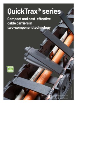
QuickTrax® series
1 /18Pages
Catalog excerpts
Jtected for the TSUBAKIKABELSCHLEPP GmbH national registration in the following countries: tsubaki-kabelschlepp.com/trademarks
Open the catalog to page 1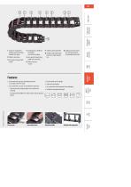
1 Sturdy 2-component design: hard chain body, flexible film hinge 2 Plastic chain links 3 Extensive unsupported length 4 Inside space is gentle on the cables- 5 Very quiet through integrated noise damping 6 Quick and easy to open 8 Dividers and height separations for cable separation 9 Single-part end connectors with and without integratable strain relief » Sturdy cable carrier design » High torsional rigidity » Very quiet through integrated noise damping » Extensive unsupported length Features » Extremely fast and easy cable laying thanks to crossbar with film hinge » Each chain link consists...
Open the catalog to page 2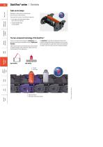
QuickTrax® series I OverviewCable carrier design Solid plastic cable carriers: chain links and end connectors made of plastic Each chain link consists of two different materials: » Hard cable carrier body made of glass fiber-reinforced material » Flexible lamellae made of elastic plastic The two-component technology of the QuickTrax® combines two seemingly incompatible features: Stability and flexibility. Cable carriers need to be extremely sturdy, with extensive unsupported length. At the same time, cables need to be inserted easily for fast cable laying. The QuickTrax® meets these requirements...
Open the catalog to page 3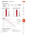
Load diagram for unsupported length depending on additional load Advantages over competitive product » 20 % longer unsupported length compared to competitive product » 33 % greater additional load through use of fiber glass reinforced plastic » Greater inner height » Low noise operation due to internal damping system » High side stability through locking in the stroke system » Dividers can be used for cable separation
Open the catalog to page 4
Unsupported arrangement
Open the catalog to page 6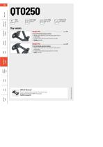
QuickTrax® series » Weight-optimised plastic frame with particularly high torsional rigidity. » Crossbar can be opened at any position on one side. » Outside: openable. » Weight-optimised plastic frame with particularly high torsional rigidity. » Crossbar can be opened at any position on one side. » Inside: openable. UNIFLEX Advanced For a non-opening cable carrier with 17.5 mm inner height we recommend the series UNIFLEX Advanced
Open the catalog to page 7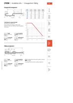
Load diagram for unsupported length depending on the additional load. Intrinsic cable carrier weight =0.36 kg/m with Bj 50 mm. For other inner widths, the maximum additional load changes. Gliding arrangement Subject to change without notice. | j The gliding cable carrier must be guided in a channel. Only design 030 can be used for a gliding arrangement.
Open the catalog to page 8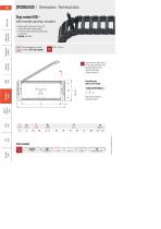
QT0250.030 I Dimensions • Technical dataStay variant 030-with outside opening crossbars » Weight-optimised plastic frame with particularly high torsional rigidity. » Crossbars can be opened at any position on one side » Outside: openable. Stay arrangement on each Bj 30 - 50 mm chain link (VS: fully-stayed) The maximum cable diameter strongly depends on the bending radius and the desired cable type. Calculating the cable carrier lengthCable carrier length Lk Lk = y+ Lb Cable carrier length Lk rounded to pitch t Stay variant Stay arrangement
Open the catalog to page 9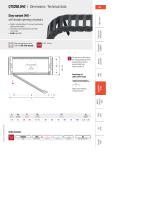
» Weight-optimised plastic frame with particularly high torsional rigidity. » Crossbars can be opened at any position on one side » Inside: openable. Stay arrangement on each Bj 30 - 50 mm chain link (VS: fully-stayed) The maximum cable diameter strongly depends on the bending radius and the desired cable type. Calculating the cable carrier lengthCable carrier length Lk Lk = y+ Lb Cable carrier length Lk rounded to pitch t Subject to change without notice. Type Stay variant Bj[mm] KR[mm] Lk[mm] Stay arrangement
Open the catalog to page 10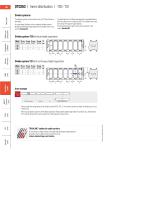
QT0250 I Inner distribution I TS0-TS1Divider systems The divider system is mounted on every 2nd chain link as a standard. As a standard, dividers or the complete divider system (dividers with height separations) are movable in the cross section (version A). For applications with lateral accelerations and applications with the cable carrier rotated by 90°, the dividers can easily be fixed on the stay through rotation. The arresting cams snap into the catch profiles in the covers (version B). Divider system TS1 with continuous height separation Order example Divider system Version or Height separation...
Open the catalog to page 11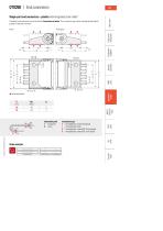
The plastic end connectors can be connected from above or below. The connection type can be changed by altering the position of the end connector. 5 Fixed point FH ^|fa Connection point Connection type F - fixedpoint A - threaded joint outside (standard) M - driver I - threaded joint inside H - threaded joint, rotated 90° to the outside K - threaded joint, rotated 90° to the inside Subject to change without notice. Order example
Open the catalog to page 12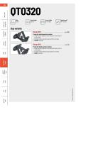
» Weight-optimised plastic frame with particularly high torsional rigidity. » Crossbar can be opened at any position on one side. » Outside: openable. Frame with inside opening crossbars » Weight-optimised plastic frame with particularly high torsional rigidity. » Crossbar can be opened at any position on one side. » Inside: openable.
Open the catalog to page 13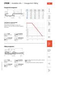
Load diagram for unsupported length depending on the additional load. Intrinsic cable carrier weight =0.40 kg/m with Bj 38 mm. For other inner widths, the maximum additional load changes. Gliding arrangement Subject to change without notice. UThe gliding cable carrier must be guided in a channel. See p. 866. Only design 030 can be used for a gliding arrangement.
Open the catalog to page 14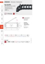
QT0320.030 | Dimensions-Technical dataStay variant 030-with outside opening crossbars » Weight-optimised plastic frame with particularly high torsional rigidity. » Crossbars can be opened at any position on one side » Outside: openable. Stay arrangement on each Bj 15 - 65 mm chain link (VS: fully-stayed) The maximum cable diameter strongly depends on the bending radius and the desired cable type. Calculating the cable carrier lengthCable carrier length Lk Lk = y+ Lb Cable carrier length Lk rounded to pitch t Stay variant Stay arrangement
Open the catalog to page 15All TSUBAKI KABELSCHLEPP catalogs and technical brochures
 QUANTUM® series
48 Pages
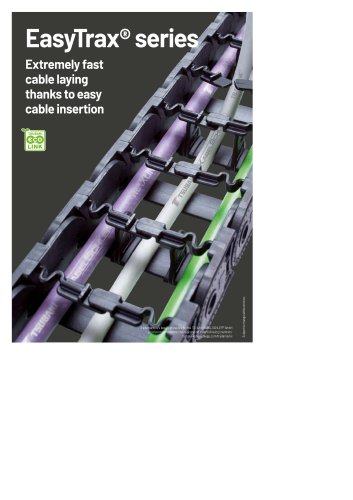 EasyTrax® series
28 Pages
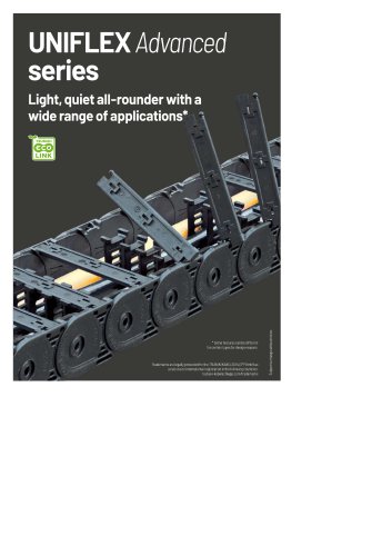 UNIFLEX Advanced series
84 Pages
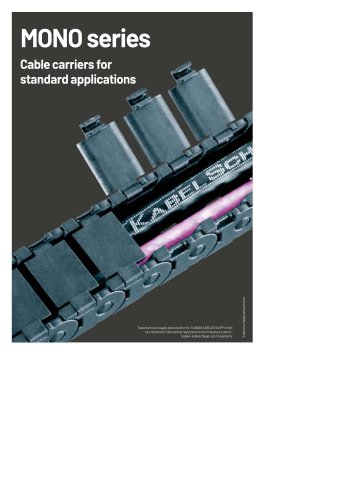 MONO series
20 Pages
- Rail conveyor
- Electrical cable
- Transport rail conveyor
- Belt conveyor
- Horizontal conveyor
- Power cable
- Insulated cable
- Insulated electrical cable
- Multi-strand cable
- Multi-wire electrical cable
- Flexible cable
- Flexible electrical cable
- PVC-sheathed cable
- PVC-sheathed electrical cable
- Halogen-free cable
- Optical cable
- Flame-retardant cable
- Halogen-free electrical cable
- Armored cable
- Flame-retardant electrical cable