
- Catalogs
- TSUBAKI KABELSCHLEPP
- QUANTUM® series


- Products
- Catalogs
- News & Trends
- Exhibitions
QUANTUM® series
1 /48Pages
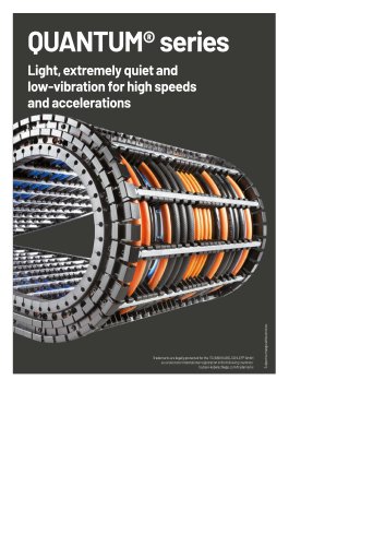
QUANTUM® series
1 /48Pages
Catalog excerpts
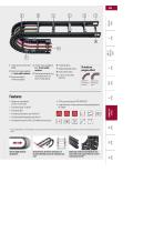
2 Aluminum stays available 3 Aluminum stays in reinforced design 4 Plastic stays available in 5 Can be opened quickly on the inside and the outside for cable laying 7 Replaceable glide shoes 8 Strain relief combs 9 C-rail for strain relief elements Virtually no polygon effect _CL> Features » Cleanroom compatible: no links, no link wear » Extremely light » For high accelerations up to 300 m/s2 » For high operating speeds up to AO m/s » Extremely long service life: > 25 million motion cycles » Large selection of stay systems and separating options for cables Side bands made from special plastic...
Open the catalog to page 2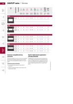
QUANTUM® series I Overview hi Iig Cable- dmax Cleanroom compatible and long service life Continuous side bands are used. In contrast to conventional hole-and-bolt connections, hardly any wear occurs (link abrasion), which makes QUANTUM® ideal for use in clean-rooms. Extremely long service life through » No link abrasion due to absence of hole-and-bolt connections » Continuous side bands made from special plastic with integrated steel cables Ideal for highly dynamic applications -extruded side bands The QUANTUM® runs extremely quietly and with low vibrations. The absence of links and the very...
Open the catalog to page 3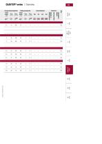
Unsupported arrangement Gliding arrangement Inner Distribution lannth VmaX amax lannth Vmax amaX
Open the catalog to page 4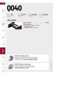
■ Plastic profile bars for light to medium loads. Assembly without screws. ■ Outside/inside: release by rotating 90°. TOTALTRAX® complete systems Benefit from the advantages of the TOTALTRAX® complete system. A complete delivery from one source - with a warranty certificate on request! Learn more at tsubaki-kabelschlepp.com/totaltrax g£* **J Hi-flex electric cables which were especially developed, ffkoptimized and tested for use in cable carriers can be found
Open the catalog to page 5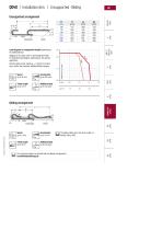
Load diagram for unsupported length depending on the additional load. Sagging of the cable carrier is technically permitted for extended travel lengths, depending on the specific application. Intrinsic cable carrier weight qx = 0.8 kg/m. For other inner widths, the maximum additional load changes. Subject to change without notice. UThe gliding cable carrier has to be routed in a channel. See p. 866. Our technical support can provide help for gliding arrangements:
Open the catalog to page 6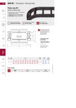
Q040RE I Dimensions • Technical data Stays on every 6th section, Stays on every 3rd section Bj 28 - 284 mm in (VS: fully-stayed) [|8 mm width sections The maximum cable diameter strongly depends on the bending radius and the desired cable type. Calculating the cable carrier lengthCable carrier length Lk QUANTUM® Type Bj [mm] Stay variant KR [mm] Lk [mm] Stay arrangement
Open the catalog to page 7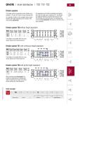
Divider systems The divider system is mounted on each crossbar as a standard - on every 6th section for stay mounting (HS), As a standard, dividers or the complete divider system (dividers with height separations) are movable in the cross section (version A). For applications with lateral accelerations and applications with the cable carrier rotated by 90°, the dividers can easily be fixed by turning the frame stay by 180°. The arresting cams click into place in the locking grids in the crossbar (version B). The groove in the frame stay faces outwards. Divider system TSO without height separation...
Open the catalog to page 8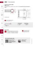
0040 IEnd connectorsUniversal end connectors UMB -plastic (standard) The universal end connectors (UMB) are made from plastic and can be mounted from the top, from the bottom or face on. O Recommended tightening torque: 5 Nm for screws M5 - 8.8 Connection point F - fixed point M - driver Connection type Order example OWe recommend the use of strain reliefs at the driver and fixed point. See from p. 924. Connection point Connection type More product information online
Open the catalog to page 9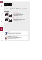
■ Aluminum profile bars for light to medium loads. Assembly without screws. ■ Outside/inside: release by rotating 90°. Frame screw-in stay ■ Plastic profile bars for light to medium loads. Assembly without screws. ■ Outside/inside: release by rotating 90°. TOTALTRAX® complete systems Benefit from the advantages of the TOTALTRAX® complete system. A complete delivery from one source - with a warranty certificate on request! Learn more at tsubaki-kabelschlepp.com/totaltrax Hi-flex electric cables which were especially developed, optimized and tested for use in cable carriers can be found at
Open the catalog to page 11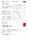
Load diagram for unsupported length depending on the additional load. Sagging of the cable carrier is technically permitted for extended travel lengths, depending on the specific application. Intrinsic cable carrier weight qx = 1.5 kg/m. For other inner widths, the maximum additional load changes. Subject to change without notice. UThe gliding cable carrier has to be routed in a channel. See p. 866. Glide shoes have to be used for gliding applications. UOur technical support can provide help for gliding arrangements:
Open the catalog to page 12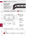
Q060RS I Dimensions • Technical dataAluminum stay RS -frame stay narrow ■ Extremely quick to open and close ■ Aluminum profile bars for light to medium loads. Assembly without screws. ■ Available customized in 1 mm sections. ■ Outside/inside: release by rotating 90°. Stays on every 6th section, Stays on every 3rd section Bj 38 - 500 mm in (VS: fully-stayed) [j1 mm width sections The maximum cable diameter strongly depends on the bending radius and the desired cable type. Please contact us. Calculating the cable carrier length Cable carrier length Lk Number of glide shoes cable carrier length...
Open the catalog to page 13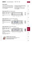
Divider systems The divider system is mounted on each crossbar as a standard - on every 6th section for stay mounting (HS), As a standard, dividers or the complete divider system (dividers with height separations) are movable in the cross section (version A). For applications with lateral acceleration and rotated by 90°, the dividers can be attached by simply clipping onto a socket (available as an accessory). The socket additionally acts as a spacer between the dividers and is available in 1 mm sections between 3 - 50 mm (version B). Divider system TSO without height separation Divider system...
Open the catalog to page 14All TSUBAKI KABELSCHLEPP catalogs and technical brochures
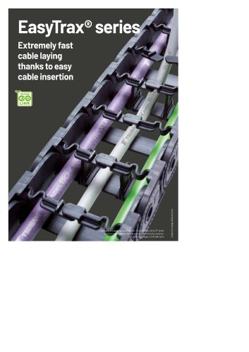 EasyTrax® series
28 Pages
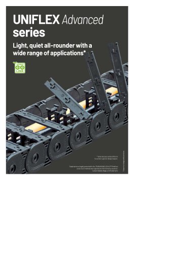 UNIFLEX Advanced series
84 Pages
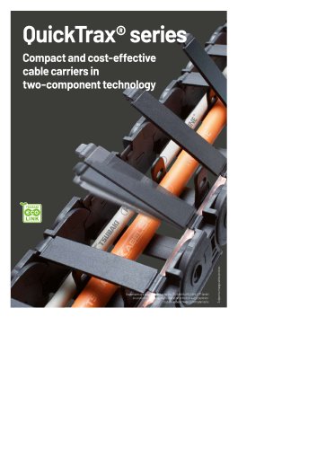 QuickTrax® series
18 Pages
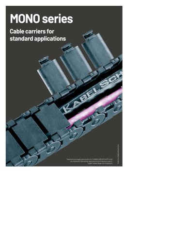 MONO series
20 Pages
- Rail conveyor
- Electrical cable
- Transport rail conveyor
- Belt conveyor
- Horizontal conveyor
- Power cable
- Insulated cable
- Insulated electrical cable
- Multi-strand cable
- Multi-wire electrical cable
- Flexible cable
- Flexible electrical cable
- PVC-sheathed cable
- PVC-sheathed electrical cable
- Halogen-free cable
- Optical cable
- Flame-retardant cable
- Halogen-free electrical cable
- Armored cable
- Flame-retardant electrical cable