Opticentric

Opticentric
Catalog excerpts

OptiCentric® Inspection, Alignment, Cementing and Assembly of Optics
Open the catalog to page 1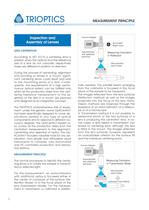
MEASUREMENT PRINCIPLE nally needed. The parallel beam emerging from the collimator is focussed in the focal plane of the sample to be measured. The images reflected from the lens surfaces (Reflection method) as well as the images projected into the focus of the lens (Transmission method) are observed through the eyepiece of an autocollimator, of a telescope or of a microscope. In Transmission method it is not possible to determine which of the two surfaces of a lens is producing the centration error. In some cases, a lens tested in transmission can reveal no centering error, although the lens...
Open the catalog to page 2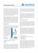
MEASUREMENT PRINCIPLE The Reflection method is the only total and true method of measurement of centration errors. However, the Reflection method is in many cases difficult to manage. On the other hand, the Transmission method with some mechanical constraints gives in many cases satisfactory results. For a good economy of the optical manufacturing both methods should be considered. When a centration error is present, the observed image describes a circle, while the sample is rotated around a reference or datum axis. The diameter of this circle is proportional with the size of the centering errors....
Open the catalog to page 3
The visual control using the eyepiece, CCDcamera, CCD-adapter optics and video monitor increases the comfort in operation, allows the operator to better concentrate on the rotation of sample, however, it has the same limitation concerning the accuracy and repeatablity. None of these equipments provides records of the centration errors or of the accuracy achieved in alignment and cementing, so that optics rejected by customers could quickly anihilate the advantage of the low price of this equipment. The use of an automated, PC-controlled Optical Sensing Head increases dramatically the accuracy...
Open the catalog to page 4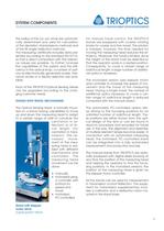
the radius of the run out circle are automatically determined and used for calculation of the deviation (transmissionn method) and of the tilt angle (reflection method). The measuring certificate includes data presented according to the standard ISO10110, so that a direct comparison with the tolerance values are possible. To further increase the capabilities of the system and the efficiency in the optical shop, a number of options as ellectronically generated scales, tolerance circles or a Yes/No selection are available. Each of the TRIOPTICS-Optical Sensing Heads can be upgraded according to...
Open the catalog to page 5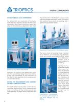
The OptiCentric® UltraStable® series provides solid and stable instrument frame, anti-vibration isolators, heavy duty air bearings and rigid tip-tilt adjustable tables. The heavy duty air bearings have a diameter of 300mm, an extremely high stiffness, axial and radial errors significantly lower than 50 nanometers and a load capacity of 500 Kg. OptiCentric® UltraStable ® series has been further developed to cover special applications in the space industry, military and astronomy. The special versions are able to support large and heavy samples with height up to 2 metres and weight up to 500 Kg....
Open the catalog to page 6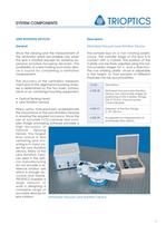
Description Motorized Vacuum-Lens Rotation Device The sample lays on a non rotating plastic chuck. The cylinder edge of the lens is in contact with a V-plate. The position of the V-plate can be finely adjusted using the two micrometers stages for x- and y-direction. The non rotating plastic chuck is adjustable in the height, so that samples of different thickness can be accomodated. SYSTEM COMPONENTS 7 LENS ROTATION DEVICES General Since the viewing and the measurement of the centration errors are possible only when the lens is rotated (except for extremly expensive errorless focussing devices),...
Open the catalog to page 7
A friction drive with different friction wheels enables the lens rotation. The position of the lens on the non rotating plastic chuck is secured by vacuum. The vacuum adapter is equipped with a precision glass window which allows viewing of the projected image, while the lens is secured by vacuum. The vacuum pump and the electronics for speed and vacuum regulation are integrated in a control module. Due to the presence of the vacuum pump, a compressed air net is not necessary. When accurately manufactured and correctly operated, this device offers very good results in accuracy and repeatability....
Open the catalog to page 8
SYSTEM COMPONENTS 9 The tip-tilt table with diameter 200 mm (TRT- 200) allows for easy and precise alignment of the samples ( 2-tilt axes, 2-translation axes) and provides the necessary stability for accurate assembly work. AB 300 air bearing series For large and heavy optical assemblies TRIOPTICS developed the UltraStable® AB 300 air bearing line. This product line is recommended for large optical assemblies Code 4-300-34 4-300-36 4-300-49 Description Air bearing rotary table AB 100, axial and radial run out less 0.05ìm, with tip-tilt table TRT-200, dia. 200mm. Including air drying unit, air...
Open the catalog to page 9
SOFTWARE 10 mount requires motorized air bearings with accurate positioning unit and reference sensor. The advanced software is designed to work under Windows XP® operating systems. The software fulfils the need of the optical shop for easy, intuitive operation and features a large number of options to accommodate a large variety of specific requirements. The software modules „Centration in Transmission“ and „Centration in Reflection“ allow for free rotation of the sample and provide an outstanding accuracy even in difficult measuring situations as poor contrast, anti-reflex coated surfaces,...
Open the catalog to page 10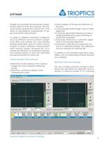
SOFTWARE 11 images and provides simultaneously measurement data for both lens surfaces. This software feature requires the OptiCentric® Dual Head for simultaneous measurement of upper and bottom lens surfaces. To adapt to different hardware configurations e.g different reticle patterns (bright cross, dark cross, pinhole, etc.), the software features selectable options. Further options enable to select different measurement units: mm/inch, arcsec, microrad, etc. To increase the efficiency in production process, the software allows to save the optimized process parameter for future use. Further...
Open the catalog to page 11All TRIOPTICS catalogs and technical brochures
 SortMaster
2 Pages
 ImageMaster-MF-200-Smart
2 Pages
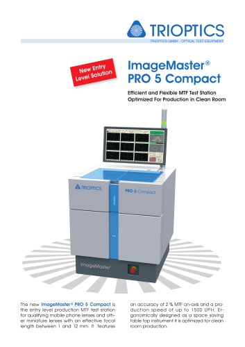
 ImageMaster-PRO-5-Compact
2 Pages
 ImageMaster-PRO-5-Ultra
2 Pages
 ImageMaster-PRO9
4 Pages
 ImageMaster-Universal-3D
4 Pages
 ImageMaster-HR-2016
4 Pages
 ATS-200
20 Pages
 Laser Rod Test Station
2 Pages
 OptiCentric® UltraPrecision
8 Pages
 OptiCentric® IR
40 Pages
 triangle
2 Pages
 Spherometers
8 Pages
 OptiSurf®
2 Pages
 S p e c t r o M a s t e r
20 Pages
 OptiSpheric
20 Pages
 ImageMaster®
21 Pages
 PrismMaster®
16 Pages
 OPTOMATIC optical test instrument
12 Pages
- Turning center
- Measuring device
- Test stand
- Sorting machine
- Thickness gauge
- Automatic sorting system
- Benchtop measuring module
- High-precision gauge
- Compact turning machine
- Surface measuring machine
- USB measuring module
- Optical gauge
- Industrial surface measuring machine
- Stationary thickness gauge
- Process measuring module
- Non-contact gauge
- Automatic calibration thickness gauge
- Interferometer
- Diameter measuring device
- Goniometer