Group: Bachofen AG

Catalog excerpts

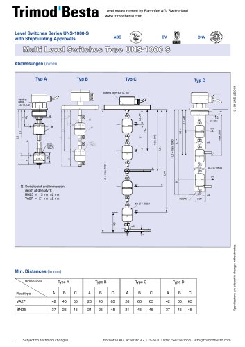
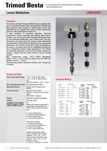
Data sheet LTDS04EN | Page 1 of 2 Top mounted level switches for level alarm or pump control applications Nominal pressure Operating temperature Ambient temperature Density of the liquid > Pump control > Alarm Operating differential Wetside material Housing material min. 0.5 kg/dm³ min. 0.5 kg/dm³ 12 to 4340 mm stainless steel (CrNiMo) seawater resistant die cast aluminium Flange dimensions square 92 x 92 mm, PCD 92 mm Switch element Microswitch SPDT with silver contacts Switch rating 250 VAC, 5 A / 30 VDC, 5 A Enclosure IP65 Weight approx. 3.0 kg Safety Integrity Level (SIL) SIL 1 Stop collar Connection diagram Vertical rods Both rods and the supplied nipple (L = 10 mm) have to be welded together as shown. Both weld seams must be smoothed, so the float can glide freely. Weld seams Installation Over open tanks or sumps on a bracket. On closed tanks on the manhole covery with the float mounted from the inside. In the absence of a manhole, i.e. the float can not be mounted from the inside, an intermediate flange with an inside diameter of min. 125 mm of flange modules acc. to EN/DIN DN125 or ANSI DN5″ should be used. We recommend, that the rod should be guided loosely at the lower end. Stop collar Flange dimensions Setting the switching differential 1. For pump control (2 switch points) The required differential is set by fixing the two stop collars in the appropriate positions on the rod. The counterweight has to be adjusted to compensate for the rod weight (without float), until the cross arm is balanced. The float slides up and down the rod with the liquid level and actuates the switch at the set position of the stop collars. The switch remains latched between the two positions, which are for applications such as pump control where the contactor coil would need to remain energized throughout the pumping cycle. 2. For alarm operation (1 switch point) Only the lower collar is fixed on the for (below the float). Within the limit of the rod length, the height of the alarm point can be chosen as required. The counterweight has to be set, to outweigh the rod (without float). The alarm switching differential is 12 mm. Quality Assurance Data Sheet LTDS04EN English, October 2015 Material certificates acc. to EN 10204-2.2 and EN 10204 3.1 Test records of hydraulic pressure tests and functional tests With reservation of technical mo
Open the catalog to page 1
Data sheet LTDS04EN | Page 2 of 2 Dual SPDT microswitches (SIL 2) Microswitches with gold plated contacts Self checking proximity switches acc. to NAMUR Enclosure IP67, or IP68 for submersible applications 380 VAC, 5 A 440 VDC, 0.3 A (type: AE26) Pneumatic switches ON/OFF High and low temperature versions Cable entry with 3/4″ NPT internal thread Switch housing: - chromated - stainless steel (CrNiMo) - epoxy painted Flange modules: - acc. to ANSI, EN/DIN, BS & JIS Marine approvals and registrations of Trimod Besta level switches Counterflanges The simplest method of installing the Trimod...
Open the catalog to page 2All Trimod'Besta catalogs and technical brochures
-
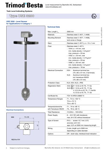 Data Sheet USE 3200
2 Pages
-
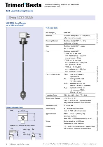 Data Sheet USE 3000
2 Pages
-
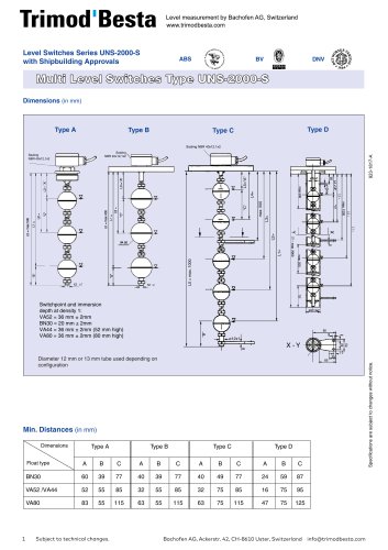 Data Sheet UNS 2000-S
2 Pages
-
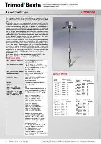 Data Sheet UNS 2000
4 Pages
-
 Data Sheet UNS 1000-S
2 Pages
-
 Data Sheet UNS 1000
4 Pages
-
 Trimod Besta Level Switch
1 Pages
-
 Specialty Switches
1 Pages
-
 KARI
KARI6 Pages
-
 Trimod'Besta Catalogue
48 Pages
-
 Data Sheet ELS-1100
1 Pages
-
 Data Sheet LS-1900T
1 Pages
-
 Data Sheet LS-74780
1 Pages
-
 Data Sheet LS-1950
1 Pages
-
 Data Sheet LS-7 range
4 Pages
-
 Data Sheet LS-3
3 Pages
-
 Data Sheet LS-1700
1 Pages
-
 Data Sheet 34000E-A
1 Pages
-
 Data Sheet 34000-A
1 Pages
-
 Data Sheet 34000E-K
1 Pages
-
 Data Sheet LS-1750
1 Pages
-
 Data Sheet LS-800
4 Pages
-
 LTB017EN
8 Pages
-
 LTB007X
24 Pages
-
 LTB006X
28 Pages
-
 LTB010X
20 Pages
-
 LTB005X
20 Pages
-
 LTB003X
16 Pages
-
 LTB008X
24 Pages
-
 Data Sheet A 01 142
2 Pages
-
 LTDS03 - A 01 090
3 Pages
-
 Shipbuilding solutions
8 Pages
-
 BLS Level Sensor
4 Pages
-
 LTDS04
2 Pages
-
 LTDS02
2 Pages
-
 LTDS01
4 Pages
-
 Trimod'Besta Brochure
16 Pages
-
 Trimod'Besta Accessories
4 Pages
-
 Trimod'Besta
16 Pages


