
- Catalogs
- Trimod'Besta
- Operating Instructions – types 140,140,145,146

Operating Instructions – types 140,140,145,146
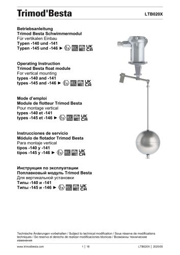
Operating Instructions – types 140,140,145,146
1. Used Symbols and Signs
- Information: Offers application tips and crucial information for optimal performance.
- Attention: Specifies requirements and prohibitions to avoid material and environmental damage.
- Danger: Warns of hazardous situations that could result in injury or death if not adhered to.
2. Setting the Switching Differential
- For pump control, adjust the differential by securing two stop collars on the rod. The counterweight should balance the rod's weight without the float.
- For alarm operation, only the lower collar is secured. The counterweight should exceed the rod's weight without the float. The alarm differential is 12 mm.
- Factory settings are designed for pump control with specific distances for types -140/-145 (32 mm) and -141/-146 (29 mm).
3. Distance X for Counterweight
- Tables specify distances for counterweights based on rod length and type.
- Types -140 and -141 have different settings compared to types -145 and -146.
- Factory settings are marked with an asterisk.
4. Installation
- Ensure the counterweight and cable entry are aligned in the same direction.
- Installation differs based on tank type: open tanks use a bracket, closed tanks use a manhole cover.
- If no manhole is present, an intermediate flange with a minimum diameter of 125 mm is necessary.
5. Additional Operating Instructions
- For electrical and pneumatic connections, consult specific operating instructions based on the type series.
6. Maintenance
- Inspect and clean float modules at least annually, following the switch operating instructions.
Catalog excerpts
LTB020X Betriebsanleitung Trimod Besta Schwimmermodul Für vertikalen Einbau Typen -140 und -141 Typen -145 und -146 ► Operating Instruction Trimod Besta float module For vertical mounting types -140 and -141 types -145 and -146 ► Mode d’emploi Module de flotteur Trimod Besta Pour montage vertical types -140 et -141 types -145 et -146 ► Instrucciones de servicio Módulo de flotador Trimod Besta Para montaje vertical tipos -140 y -141 tipos -145 y -146 ► Инструкция по эксплуатации Поплавковый модуль Trimod Besta Для вертикальной установки Типы -140 и -141 Типы -145 и -146 ► Technische Änderungen vorbehalten / Subject to technical modification / Sous réserve de modifications techniques / Se reserva el derecho de realizar modificaciones
Open the catalog to page 1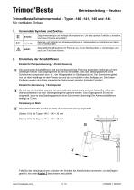
rimod'Besta Betriebsanleitung - Deutsch Einsatz fur Pumpensteuerung, 2-Punkt-Steuerung 11“ Die gewtinschte Schaltdifferenz wird durch entsprechende Fixierung der beiden Stellringe auf dem Gestange erreicht. Das Gegengewicht B) wird so eingestellt, dass das Gestangegewicht (ohne Schwimmer) kompensiert wird, d.h. der Waagebalken im Gleichgewicht ist. Der Schwimmer gleitet nun auf dem Gestange mit dem Niveau auf und ab und schaltet in den Endlagen um. Die beiden Endlagen werden durch das magnetische Drehmoment gehalten (bistabile Funktion). Einsatz fur Alarmierung, 1 Schaltpunkt Es wird nur der...
Open the catalog to page 3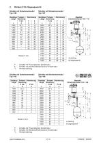
P : Schalter mit Pneumatischen Schaltmodul E : Schalter mit Elektrisch/Elektronischen Schaltmodul P : Schalter mit Pneumatischen Schaltmodul E : Schalter mit Elektrisch/Elektronischen Schaltmodul
Open the catalog to page 4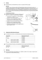
Einbau Kg3 Gegengewicht B) und Kabeleinftihrung miissen in die gleiche Richtung zeigen. In offenen Tanks und Gruben werden die Fullstandschalter direkt auf eine Konsole montiert. An begehbaren, geschlossenen Tanks erfolgt bei nachtraglicher Montage des Schwimmermoduls von der Innenseite (Mannlochdeckel). Wo kein Mannlochdeckel vorhanden ist bzw. das Schwimmermodul nicht von innen montiert werden kann, ist entweder ein Zwischenflansch mit einem Innendurchmesser von min. 125 mm oder aber die Ausfuhrung mit EN/DIN-Flanschen DN 125 oder ANSI-Flanschen DN 5“ zu verwenden. Vertikalstange montieren...
Open the catalog to page 5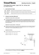
rimod'Besta Operating Instruction - English Application for pump control, 2 switch points The required differential is set by fixing the two stop collars in the appropriate positions on the rod. The counterweight B) has to be adjusted to compensate for the rod weight (without float), until the cross arm is balanced. The float slides up and down the rod with the liquid level and actuates the switch at the set position of the stop collars. The force of the magnets causes the switch to remain in either of the two end positions. Application for alarm operation, 1 switch point jj Only the lower collar...
Open the catalog to page 6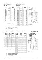
P : Switch with pneumatic module E : Switch with electrical module *) : Factory settingSwitch with float module Switch with float moduletype -145 type -146 Rod Technical drawing float module -145 / -146 P : Switch with pneumatic module E : Switch with electrical module *) : Factory setting www.trimodbesta.com 7 | 18 LTB020X | 2025/05
Open the catalog to page 7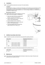
Installation IS3 Counterweight B) and cable entry must point in the same direction. Over open tanks or sumps on a bracket. On closed tanks on the manhole cover with the float mounted from the inside. In the absence of a manhole, i.e. the float can not be mounted from the inside, an intermediate flange with an inside diameter of min. 125 mm of flange modules acc. to EN/DIN DN 125 or ANSI DN 5“ should be used. Mounting the vertical rod |“|j Adjusting rings with grub screw (2 pieces) incl. tool and cotter pin 2.5x16 are supplied in a separate bag. 1. Mount the vertical rod to the cross beam with...
Open the catalog to page 8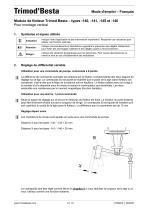
rimod'Besta Mode d'emploi - Frangais Utilisation pour une commande de pompe, commande a 2-points It La difference de commande souhaitee est obtenue par la fixation correspond ante des deux bagues de reglage sur la tige. Le contrepoids B) est ajuste de maniere que le poids de la tige (sans flotteur) soit compense, c'est-a-dire que le fleau de la balance soit en equilibre. Le flotteur glisse alors sur la tige a la montee et a la descente avec le niveau et assure la commutation aux extremites. Les deux extremites son maintenues par le moment magnetique (fonction bistable). Utilisation pour une alarme,...
Open the catalog to page 9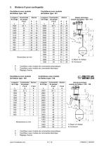
Dimensions en mm Longueur de la tige Dessin technique module de flotteur -140 / -141 P : Controleur avec module de commande pneumatique E : Controleur avec module de commande electrique *) : Reglage d'usineControleurs avec module de flotteur type -145Controleurs avec module de flotteur type -146 Longueur de la tige
Open the catalog to page 10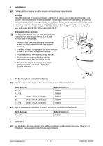
Installation HP Contrepoids B) et I'entree de cable doivent montrer dans la meme direction. Dans des reservoirs et fosses ouvertes les controleurs de niveau sont montes directement sur une console. Dans les reservoirs fermes accessibles, le montage intervient par exemple sur le couvercle du trou d‘homme avec le montage ulterieur du module du flotteur par la face interne. En l‘absence de trou d‘homme, c‘est-a-dire lorsque le module du flotteur ne peut etre monte a partir de l‘interieur, prevoir une bride intermediate ayant un diametre interieur de min. 125 mm ou bien la construction avec bride...
Open the catalog to page 11
rimod'Besta Instrucciones de servicio - Espanol Utilizacion como control de bomba, mando de 2 puntos H El diferencial de conmutacion deseado se alcanza mediante la fijacion adecuada de los dos anillos-tope en la varilla. El contrapeso B) se ajusta de manera que el peso de la varilla (sin flotador) sea compensado, es decir la varilla horizontal se encuentra en equilibrio. El flotador se desliza sobre la varilla con el nivel hacia arriba y hacia abajo y conmuta en las posiciones finales. Las dos posiciones extremas se mantienen por parte del momento magnetico (funcion biestable). Utilizacion como...
Open the catalog to page 12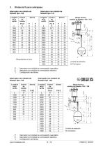
Dimensiones en mm Longitud de la varilla P : Interruptor con mOdulo de conmutaciOn neumatico E : Interruptor con mOdulo de conmutaciOn electrico *) : ConfiguraciOn de fabricaInterruptor con modulo de Interruptor con modulo deflotador tipo -145 flotador tipo -146 Longitud de la varilla P : Interruptor con mOdulo de conmutaciOn neumatico E : Interruptor con mOdulo de conmutaciOn electrico *) : ConfiguraciOn de fabrica www.trimodbesta.com 13 | 18 LTB020X | 2025/05
Open the catalog to page 13All Trimod'Besta catalogs and technical brochures
 Level Switch Catalogue
41 Pages
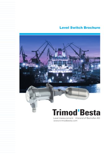 Level Switch Brochure
14 Pages
 Market Information LNG/LPG
2 Pages
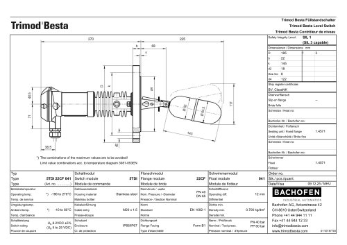 5TDI 22CF 041
2 Pages
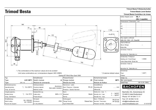 A 01 08T1
2 Pages
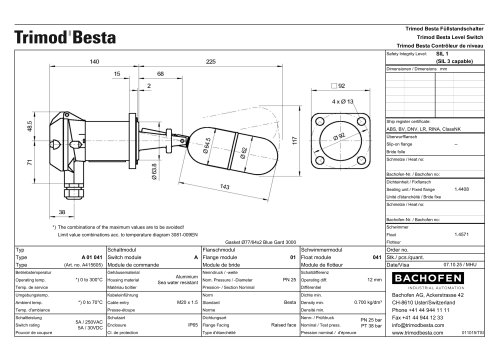 A 01 041
2 Pages
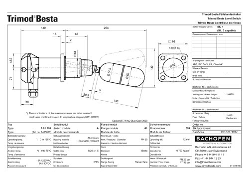 A 01 051
2 Pages
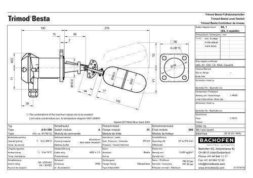 A 01 090
2 Pages
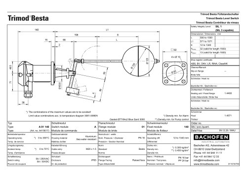 A 01 140
2 Pages
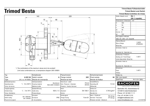 A 22C 04
2 Pages
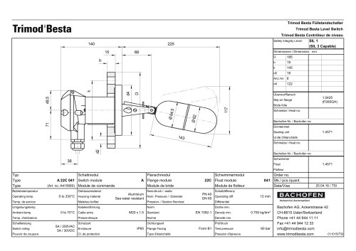 A 22C 041
1 Page
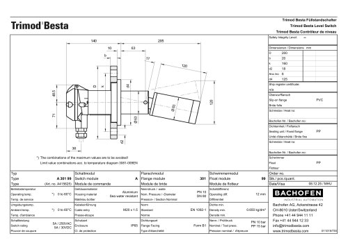 A 301 99
2 Pages
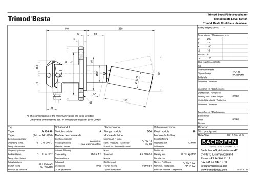 A 304 98
2 Pages
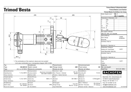 HA 24E 02
2 Pages
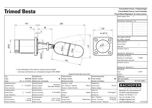 M 01 04
2 Pages
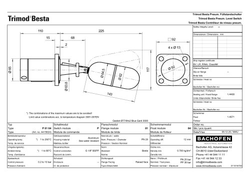 P 01 04
2 Pages
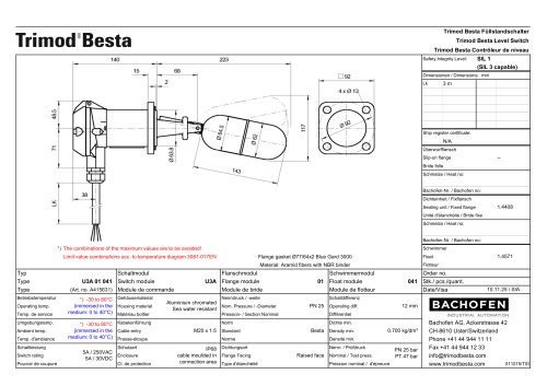 U3A 01 041
2 Pages
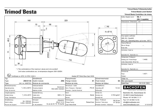 ZK8 01 04
2 Pages
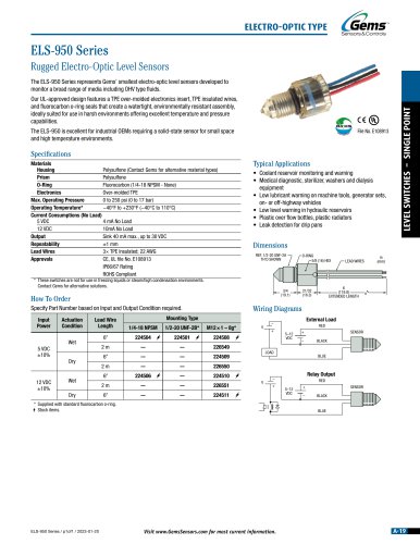 ELS-950
1 Page
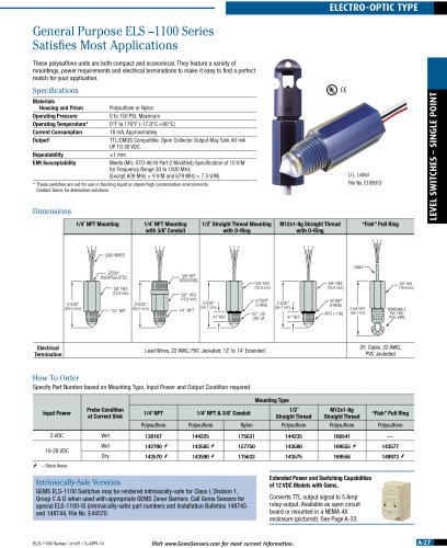 ELS-1100
1 Page
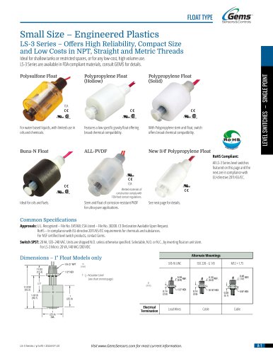 LS-3
LS-33 Pages
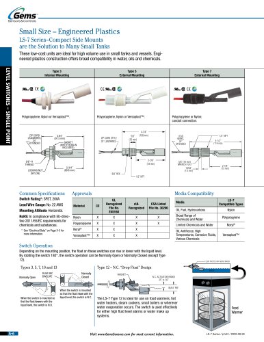 LS-7
LS-74 Pages
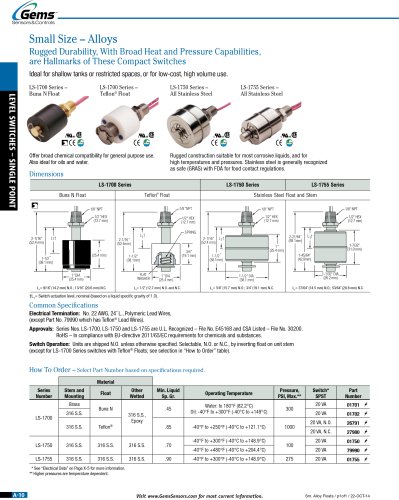 LS-1700
1 Page
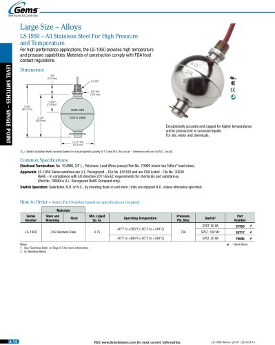 LS-1950
1 Page
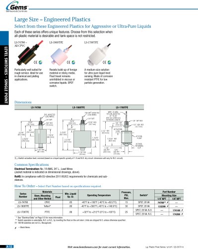 LS-74780
1 Page
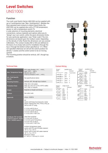 UNS 1000
4 Pages
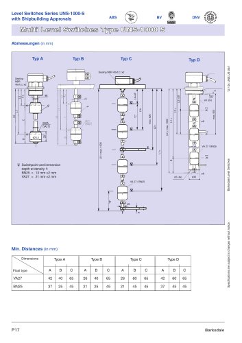 UNS 1000-S
2 Pages
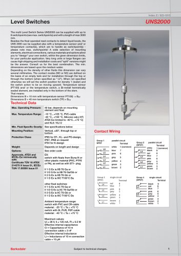 UNS 2000
4 Pages
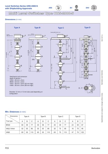 UNS 2000-S
2 Pages
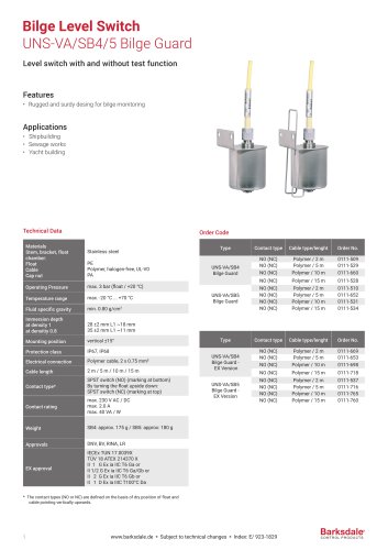 UNS-VA/SB5
2 Pages
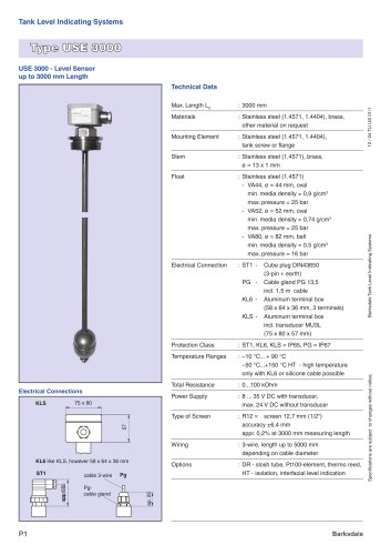 USE 3000
2 Pages
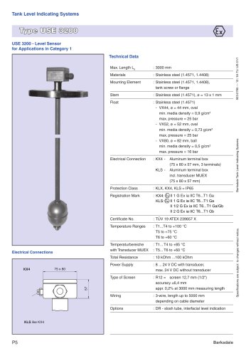 USE 3200
2 Pages






- Trimod'Besta level switch
- Trimod'Besta liquid level switch
- Trimod'Besta float level switch
- Trimod'Besta stainless steel level switch
- Level transmitter
- Liquid level transmitter
- Threaded level switch
- Analog level transmitter
- Trimod'Besta tank level switch
- Trimod'Besta magnetic float level switch
- Trimod'Besta plastic level switch
- Storage tank level transmitter
- Trimod'Besta IP65 level switch
- Trimod'Besta flange level switch
- Trimod'Besta vertical level switch
- Trimod'Besta IP67 level switch
- Compact level detector
- ATEX level switch
- Stainless steel level transmitter
- IP68 level detector