Group: Bachofen AG

Catalog excerpts

The simplest single level KARI float switches (Types 1L or 1H) have no differential (”hysteresis”). They switch on and off at one level point. Such switches work well as alarm point indicators but are unsuitable for automatic maintenance of the level of liquids in containers. Usually, tank levels are maintained by pumps or electrically-controlled solenoid valves in the supply or drain lines. The normal practice is to have two control levels involved. At one level the pump or valve is turned on and at the other level it is turned off. EXAMPLE: CONTROL OF TWO PUMPS BY USING TYPE 3H SWITCHING HEIGHT DIFFERENTIAL IN RELATIONSHIP TO THE WEIGHT FROM THE FLOAT. Switching height differential/cm SINGLE VERSUS DUAL POINT CONTROL With KARI float switches, one float switch (Type 2L or 2H) can provide ”on” and ”off” level controls. The absolute height and separation (”hysteresis”) of these points can be easily adjusted by moving the weight along the cable. The ”hysteresis” is supplied by the float switch. Other KARI float switches provide additional facilities for high and low alarms or control of duplex pump systems. Circuit closed Circuit open Low level alarm or magnetic valve control Discharging pump control or dry running prevention Circuit closed Circuit open 1 2 Circuit closed Circuit open ALARM FROM HIGH LEVEL Circuit closed Circuit open ALARM FROM LOW LEVEL KARI float switches are highly reliable. However, if a check on the operation of a particular switch is needed, it is first necessary to ascertain where the keel weight is located in order to find the ”top” point when the float is in the liquid. A good way to do this is to put the float switch on a flat surface so that it can roll freely to the working orientation (just like it does in the liquid). A continuity meter should then be attached to the circuit to be tested. Testing is then performed by tilting the float up and down in the vertical plane determined by the working orientation. At the appropriate angle, the switch circuit being tested should open or close. 1. Do not be concerned if you hear a clacking sound when the float is shaken - it is only the microswitch acting. It is extremely unusual to find any leakage in these floats. 2. Do not put the line voltage across a contact without a load attached. Shorting out the power across the microswitch will destroy it. 3. Do not tether the floats tightly on a short cable or make them jiggle and ”dance” in a high pressure washdown hose stream. The continuous ”working” of a particular point in the cable will break the wires. When the hanging clamp is used, the cable wedge must be pushed down tightly to ensure the cable doesn’t slip. 4. If the viscosity of the liquid is high, we recommend an extra weight on the cable. 5. Note that it is extremly important that the junktion box is in dry environment. If this is not possible the ends of float switch wires must be covered with e.g. protective grease. Circuit closed WIRING FOR EMPTYING OF SUMP PUMP WATER PUMPS ETC. Circuit open • alarm • start • stop • alarm It is recommended that a) Types M1H, M1L and M1C: at least 150 mm is left between float and attachment point b) Types M2H and M2L: at least 60 mm is left between float and the cable weight c) Note the ”UP” mark: install the float so that it can settle to its natural orientation VALUABLE TIPS Polypropylene Hanging Clamp and wedge (Supplied as Standard) At the same time presented with the "City of Brussels" medal VERIFYING OPERATION CHANGE OVER SWITCH Circuit closed Circuit open WIRING FOR FILLING OF STORAGE TANKS ETC. GUARANTEE Each KARI unit carries a 12 month guarantee which covers raw materials and workmanship. © 2007 Kari-Finn Oy. All Rights Reserved. Finnish quality product, exported to over 30 countries including U.S.A. and Japan. 30288 MARKPRINT OY, FINLAND, 5.2009 Charging pump control High level alarm or magnetic valve control Strain Relief Connector (Cable Gland) Change over contact (alarms etc.) There are several methods that can be used to fasten the cable so that the float is positioned at the right level in the tank. The three most commonly used are illustrated below. HEIGHT FIXING The Kari Float Switch is positioned at the right level in the tank by hanging it from the cable so that the float follows the movement of the liquids surface. The switching height differential is adjusted by moving the weight along the cable. The differential is on minimum, when the weight is nearest to the float. Wiring diagrams are also separately available on request and on our website http://www.kari-finn.fi. KARI MINI FLOAT SWITCHES, CIRCUIT DIAGRAMS FLOAT SWITCH The Kari Mini Float Switch is a control device for filling and discharging pumps, motor and magnetic valves. It is also an alarm device at certain pre-determined surface levels. SGS FIMKO OY (The Finnish Electrical Inspectorate) has perfomed the tests according Low Voltage Directive (LVD) and approved the Kari Mini Float Switch for use in non-flammable liquids at 250 Volts. For its small size (ø 76 mm) the Kari Mini Float can be used in narrow places. Gold medal at the 1977 "Brussels International Inventors Fair". Distance of the weight from float KARI MINI FLOAT MINI FLOAT SWITCH ø 76 mm Curve B shows the starting and stop height differential of the Kari Float Switch in relationship to the distance of the weight from the float. Curve C shows the equivalent differential between starting and alarm levels. For example: On type 3H, if distance of the weight from float (A) is about 50 cm, then the start / stop differential is about 50 cm and the start / alarm differential is about 12 cm.
Open the catalog to page 1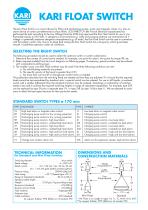
CIRCUIT DIAGRAMS } HIGH LEVEL ALARM 6...250 V Circuit closed Circuit closed Circuit open ALARM FROM HIGH AND LOW LEVEL Circuit closed Circuit open WIRING FOR FILLING OF STORAGE TANKS ETC. WIRING FOR EMPTYING OF SUMP PUMP WATER PUMPS ETC. Circuit open HIGH LEVEL ALARM Circuit open Circuit closed Circuit open Circuit closed WIRING FOR FILLING + LOW LEVEL ALARM Circuit open Circuit open Circuit closed WIRING FOR EMPTYING + HIGH AND LOW LEVEL ALARMS Circuit open WIRING FOR FILLING + HIGH AND LOW LEVEL ALARMS START ALARM WIRING FOR EMPTYING + HIGH LEVEL ALARM ALARM START Circuit closed WIRING...
Open the catalog to page 2All Trimod'Besta catalogs and technical brochures
-
 Data Sheet USE 3200
2 Pages
-
 Data Sheet USE 3000
2 Pages
-
 Data Sheet UNS 2000-S
2 Pages
-
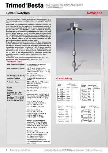 Data Sheet UNS 2000
4 Pages
-
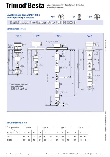 Data Sheet UNS 1000-S
2 Pages
-
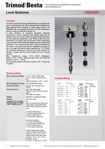 Data Sheet UNS 1000
4 Pages
-
 Trimod Besta Level Switch
1 Pages
-
 Specialty Switches
1 Pages
-
 Trimod'Besta Catalogue
48 Pages
-
 Data Sheet ELS-1100
1 Pages
-
 Data Sheet LS-1900T
1 Pages
-
 Data Sheet LS-74780
1 Pages
-
 Data Sheet LS-1950
1 Pages
-
 Data Sheet LS-7 range
4 Pages
-
 Data Sheet LS-3
3 Pages
-
 Data Sheet LS-1700
1 Pages
-
 Data Sheet 34000E-A
1 Pages
-
 Data Sheet 34000-A
1 Pages
-
 Data Sheet 34000E-K
1 Pages
-
 Data Sheet LS-1750
1 Pages
-
 Data Sheet LS-800
4 Pages
-
 LTB017EN
8 Pages
-
 LTB007X
24 Pages
-
 LTB006X
28 Pages
-
 LTB010X
20 Pages
-
 LTB005X
20 Pages
-
 LTB003X
16 Pages
-
 LTB008X
24 Pages
-
 Data Sheet A 01 142
2 Pages
-
 LTDS03 - A 01 090
3 Pages
-
 Shipbuilding solutions
8 Pages
-
 BLS Level Sensor
4 Pages
-
 LTDS04
2 Pages
-
 LTDS02
2 Pages
-
 LTDS01
4 Pages
-
 Trimod'Besta Brochure
16 Pages
-
 Trimod'Besta Accessories
4 Pages
-
 Trimod'Besta
16 Pages


