
Catalog excerpts

TECHNICAL GUIDE For Robotic Safety Clutch WIRING DIAGRAM WARNING! DO NOT DISASSEMBLE. Spring tension can cause injury. Return to Tregaskiss for service. PARTS LIST SWITCH OPERATION, REPLACEMENT & SETTING SPECIFICATIONS Certified ISO 9001:2008 Please read instructions prior to use. Save this manual for future refer
Open the catalog to page 1
WARRANTY Product is warranted to be free from defects in material and workmanship for the period specified below after the sale by an authorized Buyer. Should there be a defect please refer to our Return Merchandise Policy. PRODUCT TOUGH GUN™ Robotic MIG Guns TOUGH GUN Reamer TOUGH GARD™ Spatter Cleaner TOUGH GUN Robotic Peripherals (Clutch, Sprayer, Wire Cutter, Mounting Arms) Low-Stress Robotic Unicables (LSR Unicables) WARRANTY PERIOD 180 days 1 year 1 year 1 year 2 years Tregaskiss reserves the right to repair, replace or refund the purchase price of non-conforming product. Product...
Open the catalog to page 2
1.0 - INSTALLATION STEP #1 INSTALLING INSULATING DISC TO ROBOT Ensure robot face is in SYNC before mounting insulating disc. Install insulating disc with mounting bolts (not supplied). Torque screw 45 in.-lbs. (5 Nm). M6 STEP #2 INSTALLING CLUTCH TO INSULATING DISC Remove dust boot and install safety mount with bolts supplied. Ensure that switch assembly is facing up. Reinstall dust boot. Torque screw 45 in.-lbs. (5 Nm). NOTE: Make sure “flat” on stud is oriented in home position (between switch and air assist hole) as shown. STEP #3 INSTALLING GUN MOUNT ARM TO CLUTCH Loosen...
Open the catalog to page 3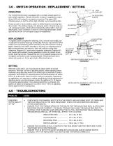
3.0 - SWITCH OPERATION / REPLACEMENT / SETTING OPERATION The TOUGH GUN Clutch is equipped with a normally closed switch for safe reliable operation. Remote indication of status is supplied by means of two LEDs (A) housed in connector on cord-set. The green LED indicates power on and the amber light indicates normal operating state. During a crash or fault condition, piston is shifted towards mounting face (B) of clutch. The shifting of piston (C) activates switch (D) and drops out +24 volt signal (output), which will be indicated by amber light in cord-set deactivating. Upon correction or...
Open the catalog to page 4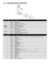
5.0 - EXPLODED VIEW & PARTS LIST NOT SHOWN NOT SHOWN NOT SHOWN 5 6 7 CLUTCH BOLT DUST BOOT M6 X 1.0 X 65 S.H.C.S. CORD SET (AS-708-14-1 & AS-708-14-2) JUMPER CABLE (12’ - 3 m WITH L.E.D.s COILED) JUMPER CABLE (15' - 5 m) CABLE ASSEMBLY 2-PC MOTOMAN MAIN CABLE ASSEMBLY MOTOMAN 5’ MAIN CABLE ASSEMBLY MOTOMAN 10’ O-RING MICRO-SWITCH ASSEMBLY SWITCH HOUSING CAP SCREW - 5-40 X 3/8 SERIAL # 0001 TO 5393 CAP SCREW - M3 X .5 X 10 AFTER SERIAL 5394 SWITCH PROTECTOR SWITCH ADJUSTING WRENCH REPLACEMENT CLUTCH (WITH JUMPER AND LONG CORD) REPLACEMENT CLUTCH (12”/3 m JUMPER CORD ONLY) VELCRO CLUTCH CABLE...
Open the catalog to page 5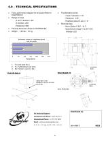
Force and moment diagram for air assist (Refer to DIAGRAM #1) Trip/Activation points - X and Y direction 1.0 - Z direction .018” - Rotational about Z axis 1.0 Physical dimension (Refer to DIAGRAM #2) Electrical data - Micro-Switch P.N.P. / N.C. - Operational voltage 10 to 30 V DC Indicator LED Activation Loads on Tregaskiss Clutch Activation Loads on Tregaskiss Clutch with Air-Assist without Air-Assist 3 Force (lbs/in) 1. Fz Axial load (lbs.) 2. Fx, Fy Bending Load (lbs.) 3. Mz Torsion Load (in.-lbs.) LOCKING SEAL ZERO REF. FOR MOMENT CALCULATIONS (Mx & My) LOCKING SEAL SEAL REMOVED
Open the catalog to page 6All Tregaskiss catalogs and technical brochures
-
 TREGASKISS™ POWER PINS
3 Pages
-
 TOUGH GUN™ TT3 Reamer
8 Pages
-
 Tregaskiss™
14 Pages
-
 AUTOMATION CATALOG
15 Pages
-
 TOUGH GUN I.C.E
2 Pages
-
 Tregaskiss Automation Catalog
13 Pages
-
 Power Pins Spec Sheet
3 Pages
-
 Control Plugs Spec Sheet
2 Pages


