
Catalog excerpts
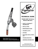
TECHNICAL GUIDE TOUGH GUN™ G2 Series Robotic MIG Guns SAFETY & WARRANTY INFORMATION INSTALLATION MAINTENANCE GUIDE TECHNICAL DATA OPTIONS EXPLODED VIEW & PARTS LIST Effective September 2010 – QUICK LOAD™ Liners Standard on all TOUGH GUN™ Robotic Air-Cooled MIG Guns Certified ISO 9001:2008 Please read instructions prior to use. Save this manual
Open the catalog to page 1
THANK YOU… …for selecting a TOUGH GUN™ G2 Series Robotic MIG Gun from Tregaskiss. Manufacturing operations demand extremely dependable robotic equipment. With this in mind, the TOUGH GUN MIG Gun was designed and engineered to be a reliable tool to support high production within a robotic cell. As the name implies, the TOUGH GUN MIG Gun is made from durable materials and components engineered to perform in a rugged welding environment. Your TOUGH GUN MIG Gun is completely assembled and ready to weld, and has undergone numerous quality checks to ensure high performance. The instructions and...
Open the catalog to page 2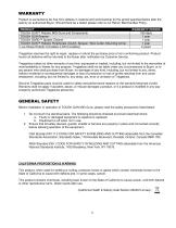
WARRANTY Product is warranted to be free from defects in material and workmanship for the period specified below after the sale by an authorized Buyer. Should there be a defect please refer to our Return Merchandise Policy. PRODUCT TOUGH GUN™ Robotic MIG Guns and Components TOUGH GUN Reamer TOUGH GARD™ Spatter Cleaner TOUGH GUN™ Robotic Peripherals (Clutch, Sprayer, Wire Cutter, Mounting Arms) Low-Stress Robotic Unicables (LSR Unicables) WARRANTY PERIOD 180 days 1 year 1 year 1 year 2 years Tregaskiss reserves the right to repair, replace or refund the purchase price of non-conforming...
Open the catalog to page 3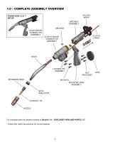
1.0 – COMPLETE ASSEMBLY OVERVIEW VELCRO WRAP TOUGH GUN I.C.E.™ SETUP UNICABLE ASSEMBLY M6 SHCS SOLID MOUNT CONNECTOR ASSEMBLY CLUTCH CABLE CLUTCH MOUNT CONNECTOR ASSEMBLY LOCKING PIN ASSEMBLY NOT PROVIDED* RETAINING HEAD M6 SHCS MOUNTING ARM ASSEMBLY NECK INSULATOR For complete parts list, please proceed to Section 7.0 – EXPLODED VIEW AND PARTS LIST. * Check with robot manufacturer for correct fastener.
Open the catalog to page 4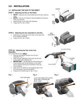
STEP 1: Attaching the Disc to the Robot NOTE: Fasteners are not provided since the size varies by NOTE: The use of a dowel is recommended and varies by robot manufacturer. Install the disc to the robot with fasteners. Torque to 45 in.-lbs. (5 Nm). STEP 2: Attaching the Arm Assembly to the Disc Install the arm assembly to the disc on the robot with 6 mm SHCS (provided). Torque to 45 in.-lbs. (5 Nm). CLUTCH STUD STEP 3A: Attaching the Gun to the Arm Assembly (For Clutch Mount Guns ONLY) Remove the fastener and pin from the arm assembly (Fig. 1). Insert the gun assembly clutch stud...
Open the catalog to page 5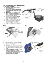
STEP 3B: Attaching the Gun to the Arm Assembly (For Solid Mount Guns ONLY) Remove the fastener and pin from the arm assembly (Fig. 1). Insert the solid mount gun assembly stud into the mounting arm on the robot until it bottoms out. IMPORTANT: The flat feature of the locking pin must interface with the flat feature on the stud to achieve locking and orientation (See Fig. 1 below). Insert the 6 mm SHCS on the opposite side of the arm and screw it into the locking pin (See Fig. 2 below). Torque 6 mm SHCS to 60 in.-lbs. (7 Nm). Insert 5 mm SHCS through solid mount gun assembly and...
Open the catalog to page 6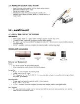
2.3 INSTALLING CLUTCH CABLE TO GUN Install the clutch cable supplied with the robotic safety clutch to the switch connection at the clutch. Tighten connection by hand. Attach clutch cable at five points along the unicable with supplied Velcro straps (or leather jacket for TOUGH GUN I.C.E. components). 3.0 – MAINTENANCE 3.1 NOZZLE AND CONTACT TIP SYSTEMS Neck insulator MUST be in place before welding to properly insulate neck armor. Check all parts to ensure that connections are tight before welding. The heavy duty retaining head MUST be tightened with a 5/8” (16 mm) wrench to prevent...
Open the catalog to page 7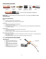
TOUGH ACCESS Consumables RETAINING HEAD NECK INSULATOR COLLER DETAIL TOUGH ACCESS CONSUMABLES ASSEMBLED INSTALLED IMPORTANT: TCP will be different from standard TOUGH LOCK™ Consumables (See Section 4.1 GUN CONFIGURATIONS). Removal and Replacement Nozzle Pull slip-on nozzles off with a twisting motion. When installing the nozzle, ensure that it is fully seated. Contact Tip Thread the contact tip into the retaining head. Torque to 30 in.-lbs. (3.5 Nm). The Tregaskiss Tip Tool (Part # 450-18 – for heavy-duty tips) or a pair of weld pliers are the optimal tools for contact tip...
Open the catalog to page 8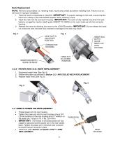
Neck Replacement NOTE: Remove consumables (i.e. retaining head, nozzle and contact tip) before installing neck. Failure to do so will result in improper installation. 1. Twist the hand nut clockwise to UNLOCK. IMPORTANT: To prevent damage to the neck, ensure that the hand nut is always in the UNLOCKED position when inserting a neck. 2. Insert the neck into the connector housing. IMPORTANT: The neck is fully inserted only when the neck bottoms out and the insertion depth guide (INSERT TO HERE) on the neck meets up with the connector housing. 3. Release the hand nut allowing it to return to...
Open the catalog to page 9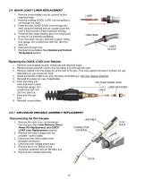
3.4 QUICK LOAD™ LINER REPLACEMENT 1. Remove consumables (nozzle, contact tip and retaining head). 2. Remove existing QUICK LOAD Liner by pulling it out through the neck. 3. Insert the new QUICK LOAD Liner through the neck using the welding wire as a guide (push the liner in short bursts to help to prevent kinking). 4. Once the liner stops feeding, give it an extra push to ensure it is inserted completely. 5. Push liner back into gun and hold in place. Using liner gauge, trim conduit liner with 3/4” (20 mm) stick out. 6. Feed wire through liner. 7. Reinstall consumables (See Nozzles and...
Open the catalog to page 10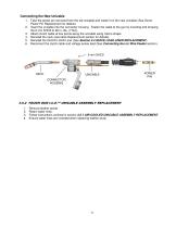
Connecting the New Unicable 1. Take the power pin removed from the old unicable and install it on the new unicable (See Direct Power Pin Replacement for details). 2. Insert the unicable into the connector housing. Fasten the cable to the gun by inserting and torquing the 6 mm SHCS to 60 in.-lbs. (7 Nm). 3. Attach clutch cable at five points along the unicable using Velcro straps. 4. Reinstall the neck (see Neck Replacement section for details). 5. Reinstall the QUICK LOAD Liner (See Section 2.4 QUICK LOAD LINER REPLACEMENT). 6. Reconnect the clutch cable and voltage sense lead (See...
Open the catalog to page 11All Tregaskiss catalogs and technical brochures
-
TREGASKISS™ POWER PINS
3 Pages
-
TOUGH GUN™ TT3 Reamer
8 Pages
-
Tregaskiss™
14 Pages
-
AUTOMATION CATALOG
15 Pages
-
TOUGH GUN I.C.E
2 Pages
-
Tregaskiss Automation Catalog
13 Pages
-
Power Pins Spec Sheet
3 Pages
-
Control Plugs Spec Sheet
2 Pages


