
- Catalogs
- TRANSMILLE
- 4000 Series Operation Manual

4000 Series Operation Manual

4000 Series Operation Manual
The 4000 Series Precision Multi Product Calibrator by Transmille Ltd. is a versatile tool designed for accurate calibration across multiple product types. It features advanced accuracy, true multiproduct calibration capabilities, and options for retrofitting. The device includes a USB interface for connectivity and various output connections.
An unlock code is required after a 60-day evaluation period, provided by Transmille Ltd. upon payment.
The calibrator complies with European Directives for Low Voltage and EMC, carrying the CE Mark, and adheres to standards such as EN 61326-1 and IEC 61010-1.
Initial inspection, proper positioning, and connection setup are crucial. Detailed instructions are provided for setting the line voltage, connecting to a computer, and powering up the device.
Safety warnings are emphasized. The manual explains the use of front panel controls, including a numerical keypad, function keys, and a touchscreen interface. It also covers digital control and USB connectivity.
Diagrams for various connections, including AC/DC voltage and current, resistance, capacitance, inductance, frequency, and more, assist in setup and operation.
Procedures for setting various outputs, such as DC/AC voltage and current, resistance, capacitance, inductance, and frequency, are detailed. Advanced options like thermocouple simulation and power calibration are also covered.
Instructions for creating and importing procedures facilitate automated calibration processes.
Outlines the equipment required and steps for configuring and performing verification measurements to ensure accuracy and reliability.
- AC/DC Volts up to 1025 V
- AC/DC Current up to 30 Amps, extendable to 1500 Amps with an adapter
- Resistance measurement up to 1 GΩ
- Capacitance up to 100 mF
- Inductance up to 10 H
- Frequency up to 10 MHz
- Various simulation options for temperature and power harmonics
- USB and optional GPIB interface for connectivity
The calibrator integrates powerful calibration capabilities with built-in software for procedure management and record-keeping. It boasts a basic DC accuracy of 8ppm and is designed for true multiproduct calibration.
Allows for additional functions to be added through internal retrofit options, such as oscilloscope and power calibration.
The USB interface allows full programmability and easy connection to PCs, reducing setup time for on-site calibration.
The output terminal configuration matches most multimeter input connections, eliminating the need for lead changes during calibration.
High-quality screened cables with gold-plated 4mm plugs are required for voltage and low current leads. These cables must withstand 1025 volts AC and have an insulation resistance greater than 1TΩ.
The calibrator features a self-test function to monitor for overloads or faults, automatically entering standby if issues are detected. High voltage timeout is set to 20 minutes for DC and low-frequency AC, and 3 minutes for high-frequency AC.
The front panel includes a custom rubber keyboard and touchscreen interface, sealed against moisture and dirt. It features a numerical keypad, multiplier keys, function keys, and range adjustment keys.
The 7-inch LCD touchscreen displays output values, instrument status, and provides connection help prompts.
Options for running procedures, importing/exporting data via USB, and manual calibration are available. The configuration menu allows viewing and setting passcodes, test report numbers, language settings, and firmware updates.
Only qualified personnel should operate the calibrator, ensuring protection from electric shock.
Outlines procedures for configuring the calibrator, including setting passcodes, test report numbers, and language preferences.
Instructions for backing up and restoring calibration data are provided.
Details the process for updating firmware via USB, highlighting the importance of using a FAT32 formatted memory stick.
Explains how to configure communication with an external reference multimeter.
Detailed descriptions of terminal functions and connection diagrams for various outputs are provided.
Discusses the use of 'soft' keys for additional functions and provides safety warnings regarding terminal usage.
Ensure firmware updates are performed with caution to avoid data loss. Utilize the grounding function to reduce noise and prevent damage. Follow connection diagrams closely to ensure correct setup and operation.
Explains how to configure calibrator outputs by entering numerical values followed by multiplier and function keys to specify units like Volts, Amps, and Ohms.
Users can adjust the display digits using digital controls or arrow keys.
Allows users to toggle between manual and locked ranges to prevent output perturbations during linearity measurements.
Most voltage ranges have sufficient compliance current, except for the 200mV AC/DC range.
Procedures for setting DC and AC voltage and current outputs are detailed.
Instructions for setting 2-wire and 4-wire resistance outputs are provided.
The manual provides comprehensive guidance on using the 4000 series calibrator, emphasizing safety and precision in setting and adjusting electrical outputs.
Allows for resistance measurement in both 2-wire and 4-wire modes.
The calibrator can be used with optional current coils to produce high currents up to 1500A.
Supports both passive and simulated capacitance modes.
Inductance can be set using standard inductors of fixed values.
Can simulate various thermocouple types by setting the corresponding voltage output.
Uses a precision TCXO to provide frequency outputs from 1Hz to 1MHz.
Using the EA003 Optical Tachometer Calibration Adaptor, the calibrator can set RPM values from 60 to 60000 RPM.
To calibrate using the EA003 Tachometer adapter, connect it to the calibrator, select the correct range, and input the desired RPM.
The calibrator can output a mark space ratio within 100Hz to 10kHz.
Uses fixed resistors to simulate temperatures from -100°C to 800°C.
Simulates PRT values for various RTD types.
Can simulate AC power by outputting voltage and current with a phase relationship.
Outputs DC voltage and current.
Simulates harmonics and transients.
Provides amplitude, timebase, and bandwidth outputs.
Emphasizes the use of soft keys and touchscreen buttons for direct selection and adjustment of calibration parameters.
Outlines the maximum frequency capabilities of different scope options.
Instructions for adjusting level stroke amplitude and selecting the fast rise function.
Allows automated procedures to be run without computer control.
Designed for laboratories, this mode accelerates the verification and adjustment process.
Supported reference multimeters include Transmille 8081 and Fluke 8508A.
Warns about the high voltages the calibrator can produce and stresses the importance of safe programming practices.
Commands are structured using a separator '/' between each command/data pair, followed by a carriage return '<CR>'.
Provides commands for setting DC voltage ranges from 200mV to 10kV.
Similar to DC, but includes frequency settings.
Commands for DC current range from 200uA to 30A.
Includes frequency settings.
Commands for resistance range from 0 Ohms to 1G Ohms, with options for 2 or 4 wire modes.
Fixed ranges from 1nF to 10uF.
Options for simulated resistance and variable capacitance are provided with specific command sequences.
Frequency settings range from 1Hz to 10MHz.
The calibrator will reject commands that exceed range limits and will beep to indicate errors.
The ProCal calibration software utilizes these commands to ensure safe operation and proper state management between tests.
Outlines the command structure for setting frequency modes in a calibrator.
Pulse width modulation is activated with R59, allowing frequency settings from 100 Hz to 10 kHz.
Inductance settings use range commands combined with standby commands.
Commands for setting PRT values use range commands with standby commands.
Variable PRT settings involve range commands, R0 values, and output values.
Thermocouple simulation requires an EA001A adapter and involves commands for mode activation, cold junction type, thermocouple type, and output value.
Commands for oscilloscope calibration include amplitude and timebase settings.
Details various command sequences for different calibration functions.
The 4000 Series calibrators utilize advanced technology for cost-effective and high-performance calibration.
Ensure the power cord is disconnected before removing covers to avoid shock risk.
To access the front panel fuses, remove the screws on both sides of the front panel assembly.
This board provides a linear power supply for the calibrator.
Controls all calibrator functions except the high voltage safety cut-out.
Generates AC and DC voltages and currents.
Outputs above 20V use a 150W IC amplifier with thermal and overload protection.
A low voltage high current amplifier powered from an unregulated 9V 30A supply.
Six high stability current shunts provide feedback for current ranges.
Transmille offers online training to demonstrate common measurement errors and techniques to reduce them.
Maintenance includes electrical safety checks, fan cleaning, and external case cleaning.
Transmille guarantees the instrument for 3 years under normal use.
Instructions for installing USB interface drivers on Windows XP, Vista, and 7 are provided.
Catalog excerpts

4000 Series Precision Multi Product Calibrator Operation Manual Version 1.00 : September 2015 All product names are trademarks of their respective companies
Open the catalog to page 1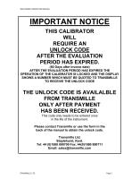
4000 SERIES OPERATION MANUAL IMPORTANT NOTICE THIS CALIBRATOR WILL REQUIRE AN UNLOCK CODE AFTER THE EVALUATION PERIOD HAS EXPIRED. (60 Days after invoice date) AFTER THE EVALUATION PERIOD HAS EXPIRED THE OPERATION OF THE CALIBRATOR IS LOCKED AND THE DISPLAY SHOWS A NUMBER WHICH MUST BE QUOTED TO TRANSMILLE TO RECEIVE THE UNLOCK CODE THE UNLOCK CODE IS AVAILALBLE FROM TRANSMILLE ONLY AFTER PAYMENT HAS BEEN RECEIVED. This code only needs to be entered once in the life of the instrument. Please contact Transmille or use the form in the back of the manual to obtain the unlock code. Transmille Ltd....
Open the catalog to page 2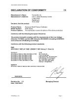
4000 SERIES OPERATION MANUAL DECLARATION OF CONFORMITY Manufacturer’s Name: Manufacturer’s Address: Transmille Ltd. Unit 4, Select Business Centre Lodge Road Staplehurst TN12 0QW Declares, that the product Product Name: Model Number: Product Options: Advanced Multi-Product Calibrator 4000 Series This declaration covers all options of the above product(s) Conforms with the following European Directives: The product herewith complies with the requirements of the Low Voltage Directive 73/73EEC and the EMC Directive 89/336/EEC (including 93/68/EEC) and carries the CE Marking accordingly Conforms...
Open the catalog to page 3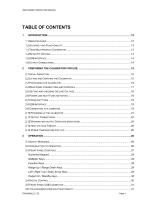
4000 SERIES OPERATION MANUAL
Open the catalog to page 4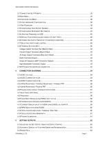
4000 SERIES OPERATION MANUAL
Open the catalog to page 5
4000 SERIES OPERATION MANUAL
Open the catalog to page 6
4000 SERIES OPERATION MANUAL
Open the catalog to page 7
4000 SERIES OPERATION MANUAL
Open the catalog to page 8
4000 SERIES OPERATION MANUAL
Open the catalog to page 9
4000 SERIES OPERATION MANUAL
Open the catalog to page 10
4000 SERIES OPERATION MANUAL
Open the catalog to page 11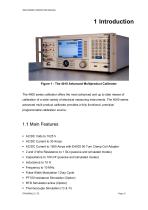
4000 SERIES OPERATION MANUAL Figure 1 - The 4010 Advanced Multiproduct Calibrator The 4000 series calibrator offers the most advanced and up to date means of calibration of a wide variety of electrical measuring instruments. The 4000 series advanced multi product calibrator provides a fully functional, precision programmable calibration source. Main Features AC/DC Volts to 1025 V AC/DC Current to 30 Amps AC/DC Current to 1500 Amps with EA002 50 Turn Clamp Coil Adapter 2 and 4 Wire Resistance to 1 G (passive and simulated modes) Capacitance to 100 mF (passive and simulated modes) ...
Open the catalog to page 12
4000 SERIES OPERATION MANUAL DDS Power / Power Harmonics Generation (Internal Option) 350/620 MHz Oscilloscope Calibration (Internal Option) 6400MHz High Bandwidth Oscilloscope Output USB Interface GPIB (IEEE488) Interface Option Extendable via Range of Adaptors utilising the Adapter Interface Accuracy and Functionality The 4000 series integrates powerful calibration capabilities using built-in software. This system provides total functionality including procedure management, calibration record keeping and built-in PCL printer connectivity for direct printout of reports. The 4010...
Open the catalog to page 13
4000 SERIES OPERATION MANUAL Retro Fit Options Allows additional functions to be added. Several internal retrofit options including oscilloscope, power, inductance and PRT allow the user to select the most cost effective solution for the calibration work with the ability to add extra functions at a later date. External options for the calibration of clamp meters, high accuracy thermocouple simulation with auto CJC (cold junction compensation) built into the TC (thermocouple) connector, optical tachometers, torque drivers etc. are also available via the front panel adapter interface. USB Interface...
Open the catalog to page 14
4000 SERIES OPERATION MANUAL 2 Preparing The Calibrator for Use. Initial inspection After shipment the calibrator should be inspected for any signs of external damage. Should external damage be found contact the carrier immediately. Do not connect a damaged instrument to the line power as this may result in internal damage. Please retain the original packaging; this should be used when returning the calibrator for service and recalibration. Lifting and Carrying the Calibrator Note: Observe all normal practices for health and safety when carrying heavy items. The calibrator weighs 23kg with most...
Open the catalog to page 15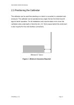
4000 SERIES OPERATION MANUAL Positioning the Calibrator The calibrator can be used free standing on a bench or mounted in a standard rack enclosure. The calibrator can be operated at any angle; the two front feet have tilt legs for bench operation. For all installations care must be taken not to cover the ventilation slots underneath or block the fan. A 2” (5cm) space behind the instrument is also required for line and interface connections. Minimum 2” (5cm) Figure 2 - Minimum Clearance Required
Open the catalog to page 16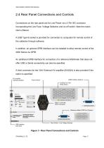
4000 SERIES OPERATION MANUAL Rear Panel Connections and Controls Connections on the rear panel are for Line Power via a 3 Pin IEC connector incorporating the Line Fuse, Voltage Selection and on-off switch. Note the mains inlet is filtered. A USB Type B socket is provided for connection to computers for remote control of the calibrator through software. In addition, an optional GPIB Interface can be installed to allow remote control of the 4000 Series via GPIB. An additional GPIB interface for connection of a reference Multimeter that does not offer USB or Serial connectivity can also be specified....
Open the catalog to page 17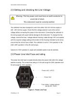
4000 SERIES OPERATION MANUAL Setting and checking the Line Voltage Warning: The line power cord must have an earth conductor to avoid risk of shock. This instrument must be correctly earthed. The calibrator has been designed to work from either 100-120 Volt line supply or 200 - 240 Volt line supply. Check that the voltage selector is set at the correct voltage before connecting the power to the instrument. Connecting the calibrator to the wrong supply will cause internal damage to the instrument. To change the line voltage, remove the fuse / voltage selector housing, rotate through 180 and...
Open the catalog to page 18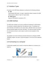
4000 SERIES OPERATION MANUAL Interface Types Connection to the 4000 Series calibrators is achieved by the following interfaces: USB Using supplied USB cable. If a longer / replacement cable is required, the 4000 Series requires a USB 2.0 Type A to Type B cable. GPIB (option) Requires GPIB cable for connection to PC. USB Interface The 4000 series calibrator can be fully controlled and calibrated via USB interface. The interface is optically isolated from the calibrator circuitry. The calibrator can send information with reference to the output status, calibration factors and value of internal...
Open the catalog to page 19All TRANSMILLE catalogs and technical brochures
 8104 - Extended Specifications
16 Pages
 9000 Series Brochure
9 Pages
 1000 SERIES
14 Pages


Archived catalogs
 3000A Series
16 Pages
 3200B
3200B10 Pages


- Management software solution
- Automation software solution
- Analysis software solution
- Process software
- TRANSMILLE Windows software
- IO module
- Cloud-based software
- Analog I/O
- Portable tester
- Industrial software
- Measurement software
- Interface software
- Automatic tester
- Generator
- Automated software
- Voltage testing system
- Analog IO module
- Network software