
- Catalogs
- Transfluid
- HF - MFO POWER TAKE OFF

- Company
- Products
- Catalogs
- News & Trends
- Exhibitions
HF - MFO POWER TAKE OFF
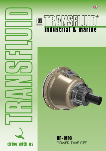
HF - MFO POWER TAKE OFF
- Elimination of pilot bearing inside the engine flywheel.
- Self-adjusting clutch for reduced maintenance.
- Unique greased-for-life bearing design.
- High torque capacity and compact design.
- Optional remote control operation.
- Dust-proof for harsh environments.
- Maximum speed ranges from 2100 to 2800 rpm depending on the model.
- Maximum input torque varies, with the highest being 7750 Nm for model 318.
- Thermal clutch capacity and lubrication methods (grease or oil) are specified for each model.
- Installation is simplified with no pilot bearing alignment required.
- Kevlar friction discs are recommended for heavy-duty applications.
- Regular maintenance involves checking the thermal capacity and ensuring proper lubrication.
Catalog excerpts

HF - MFO POWER TAKE OFF HFR - FOR SIDE LOAD AND IN-LINE SELF SUPPORTING DESIGN ELIMINATES SIDE LOADS ON THE ENGINE FLYWHEEL Self adjusting clutch Easy maintenance due to special clutch pack design Eliminates the pilot bearing inside the engine flywheel MFO - FOR SIDE LOAD AND IN-LINE SELF SUPPORTING DESIGN ELIMINATES SIDE LOADS ON THE ENGINE FLYWHEEL HFO - FOR SIDE LOAD APPL Large bearings for high side load capacity Rotary union protection Rotary union for high reliability Self adjusting clutch Easy maintenance due to special clutch pack design HF-MFO power take off - 2605
Open the catalog to page 2
OIL / AIR ACTUATION • remote control operation by push button engagement • self adjusting; no operator adjustment required • compact design • high torque capacity • eliminates the engine flywheel pilot bearing (HFO) • no side load on flywheel (HFR and MFO) • dust proof for harsh environmental conditions • simplified service in case of discs replacement • easy installation • Kevlar friction discs for heavy duty and torsionally severe applications. The MFO mechanical power take-off consists of a lever actuated clutch with a shaft and bearings mounted in a rigid cast housing. It is designed for...
Open the catalog to page 3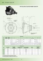
HFR OIL/AIR ACTUATED POWER TAKE OFF Heat exchanger only on HFR 314 - 318 Support palte (see TF6229) not required for HFR 210-211-311 - For permissible radial loads see selection instructions - Dimensions are subject to alteration without notice * For inline applications, with radial load, the limit decreases
Open the catalog to page 4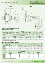
HFO OIL ACTUATED POWER TAKE OFF High radial load capability - Dimensions are subject to alteration without notice HF-MFO power take off - 2605
Open the catalog to page 5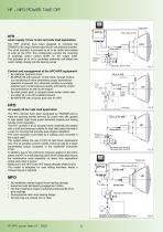
trasmissioni industriali oil/air supply 12 bar in-line and side load application The HFR clutches have been designed to complete the TRANSFLUID range of power take offs for new potential markets. The oil-air actuation is provided by oil or air radial inlet instead of axial as the HFO: this configuration permits the mounting of couplings and/or cardan shafts on the output shaft. The actuation oil or air is controlled externally and enters the clutch radially directly into the bearing carrier. Pressure switch Oil power pack for HFO Control and management of the HFO-HFR equipment: By customer hydraulic...
Open the catalog to page 6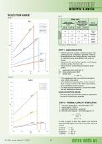
SELECTION GUIDE Chart. 1 HF... MFO HF-MFO power take off - 2605 * According to AGMA standard STEP 1 - QUICK SELECTION • Uniform load: fluid coupling, marine propulsion, fan, centrifugal pump, compressor, generator, water jet. • Moderate shock: road milling machine, cone crusher, volumetric pump, snow blower, drill, pump for dredge. • Heavy shock 1: jaw crusher, impactor, wood chipper, shredder, grinder, hammer mills. • Heavy shock 2: reciprocating compressor, piston pumps. kW : gross engine power (kW) • PTO engagement has to be performed at approximate engine idling speed. • Interval between...
Open the catalog to page 7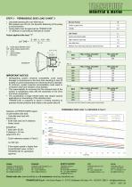
STEP 3 - PERMISSIBLE SIDE LOAD CHART 3 • Calculated bearing life over 5000 hours • Rim speeds over 35 m/s, the dynamic balancing of the pulley is recommended • Timing belts must be approved by TRANSFLUID • “X” distance is according to belt type & number Actual applied side load “T” D : pulley pitch diameter (mm) kW : gross engine power (kW) n : (rpm) S : service factor L : life factor IMPORTANT NOTICE • Disregarding system torsional compatibiliy could cause damage to components in the drive train resulting in loss off mobility or power transmission for which the drive is intended. At minimum,...
Open the catalog to page 8All Transfluid catalogs and technical brochures
 K - CK - CCK FLUID COUPLINGS
8 Pages
 KX FLUID COUPLINGS KX SERIES
4 Pages
 HYBRID & ELECTRIC TECHNOLOGY
16 Pages
 ELECTRIC PROPULSION SYSTEMS
28 Pages
 Batteries
4 Pages
 GEAR COUPLINGS P SERIES
12 Pages
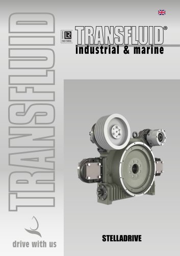 STELLADRIVE
8 Pages
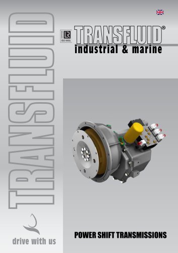 POWER SHIFT TRANSMISSIONS
8 Pages
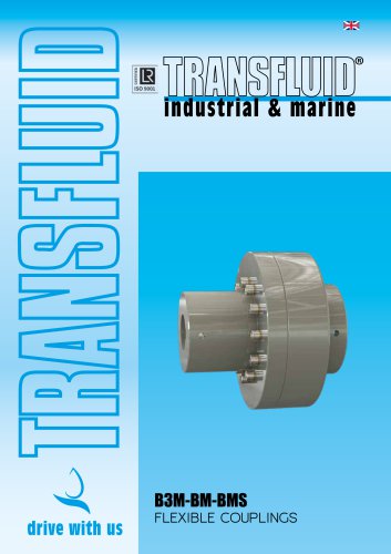 B3M-BM-BMS FLEXIBLE COUPLINGS
12 Pages
 TPO-TPH
6 Pages
 SH-SHC OIL ACTUATED CLUTCHES
8 Pages
 SL SPRING LOADED BRAKES
4 Pages
 Production range
5 Pages
 Marine Transmissions brochure
16 Pages
 TowerClutch
8 Pages
 High Speed
8 Pages




- Electromotor
- DC electromotor
- Synchronous motor
- Alternating current motor
- Asynchronous motor
- Electromotor for industrial applications
- Three-phase motor
- Compact electromotor
- Flexible coupling
- High-efficiency electromotor
- Transfluid shaft coupling
- Friction brake
- Permanent magnet motor
- Transfluid flange coupling
- Pack unit
- Torque coupling
- Spring brake
- Transmission coupling
- Electric hydraulic power unit
- Disc brake