
- Catalogs
- Transfluid
- B3M-BM-BMS FLEXIBLE COUPLINGS

- Company
- Products
- Catalogs
- News & Trends
- Exhibitions
B3M-BM-BMS FLEXIBLE COUPLINGS
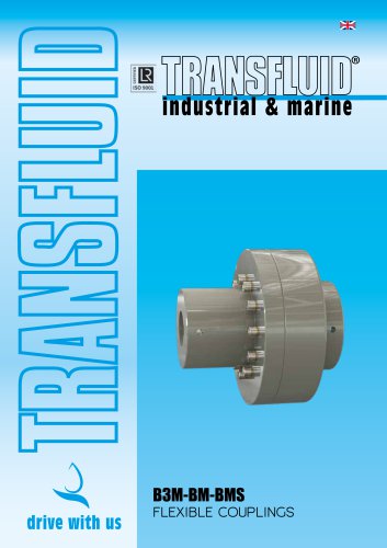
B3M-BM-BMS FLEXIBLE COUPLINGS
The B3M/BM/BMS series of flexible couplings by TRANSFLUID are designed for shaft-to-shaft applications, offering robust construction, excellent misalignment capabilities, and easy installation. These couplings require minimal maintenance, primarily periodic inspection and replacement of rubber elements. The B3M version allows for easy inspection and removal of rubber elements without disturbing alignment. Manufactured in Italy, these couplings are available in 17 sizes with torque capabilities exceeding 33100Nm.
- Compensation for misalignments
- Shock and vibration damping
- Fail-safe with high overload capacity
- Quick and easy replacement of flexible elements
- Maintenance-free
- Shaft Couplings: Standard version for connecting two shafts, allowing flexible element changes without axial movement.
- Brake Drum and Disc Couplings: Available with brake drum or disc, compatible with TRANSFLUID brakes.
- Spacer Couplings: B3M with removable spacer for easy maintenance.
- ATEX Versions: BM series couplings can be certified for use in hazardous zones according to directive 2014/34/UE (Atex).
Technical specifications include nominal torque, maximum torque, dynamic torsional stiffness, and maximum RPM for various coupling sizes. The document provides detailed tables for IEC and NEMA electric motors, outlining motor power, shaft dimensions, and corresponding coupling sizes.
The selection process involves ensuring the operating conditions do not exceed the coupling's maximum allowable load. For non-cyclic torque loads, selection is based on driving torque and service factors. For cyclic loads, a torsional analysis is required. The document outlines steps for calculating driving torque and selecting the appropriate coupling size based on various factors such as service, temperature, and starting factors.
Service factors are provided for various applications, including agitators, blowers, compressors, conveyors, cranes, fans, and more. These factors help in selecting the appropriate coupling based on the type of prime mover and application.
Detailed dimensions and specifications for B3M, B3MB, and B3MBP couplings are provided, including maximum bore sizes, weight, and inertia values. The document emphasizes that dimensions are subject to change without notice.
The document provides detailed specifications for flexible couplings, including dimensions, materials, and tolerances. Key specifications include metric and inch max bore with keyway, H tolerance, and PD2 values. Dimensions are subject to change without notice.
Installation and maintenance guidelines are provided for flexible couplings. It is recommended to perform the best possible alignment during installation, especially for rotational speeds higher than 1800 rpm. Balancing is required according to ISO 1940 standards, with specific recommendations for speeds over 2800 rpm.
The document outlines safety standards, emphasizing the need for proper protection guards during operation. It also specifies the materials used for various components, such as cast iron and steel, and provides guidelines for replacing rubber elements.
Several tables are included, detailing dimensions, misalignment values, screw tightening torque, and rubber element types and quantities. These tables provide critical data for ensuring proper installation and maintenance of the couplings.
- Maximum rotational speed and misalignment values are specified.
- Balancing recommendations for high-speed applications.
- Safety precautions and material specifications are highlighted.
- Contact information for Transfluid offices worldwide is provided.
Catalog excerpts
FLEXIBLE COUPLINGS
Open the catalog to page 1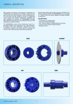
With decades of experience and thousands of applications on TRANSFLUID fluid couplings the BT flexible coupling line has been expanded to include couplings for shaft-to-shaft application. The new series has been studied to provide an exceptionally robust coupling with excellent misalignment capabilities and easy installation and assembly. The B3M/BM/BMS couplings high quality flexible elements provide reliable performance while protecting the coupled machines. The B3M/BM/BMS require minimal maintenance except for a periodical inspection and replacement of the rubber elements. To simplify in this...
Open the catalog to page 2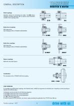
GENERAL DESCRIPTION Shaft couplings Standard version for connecting two shafts. The B3M allows changing of flexible elements with no need for axial movement of either of the couplings hubs. Brake drum couplings With brake drum. See Catalogue 355 for TRANSFLUID BRAKES. Brake disc couplings With brake disc. See Catalogue 355 for TRANSFLUID BRAKES. Spacer couplings B3M with removable spacer. Combination For connection with a TRANSFLUID fluid coupling. KRD + B3M ATEX VERSIONS It is possible to get BM series couplings, with finished bores, certified as equipment for intended use in hazardous zones...
Open the catalog to page 3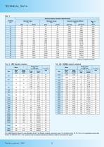
Tab. 2-2A Selection based on max allowable bore of the flexible coupling, assuming value 1 for all factors (Sm, St, Sz, SAtex). For applications where the factors are different from 1, the coupling must be properly selected according to selection procedure at page 4
Open the catalog to page 4
The coupling must be selected so that the operating conditions of the coupling, do not exceed the maximum allowable load of the coupling itself. For driving machines not generating cyclic torque loads the selection of the coupling can be performed using the driving torque and the corresponding service factor. When the driving machine generates cyclic torque loads (e.g. internal combustion engines) the selection of the coupling must be checked by a torsional analysis of the complete system. Steps to be followed are as follows. 1) Using the power and rotational speed, calculate the torque of the...
Open the catalog to page 5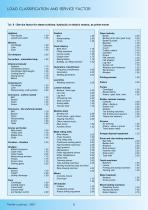
Car pullers - intermittent duty 1.50 Chemical industry Conveyors - uniform loaded Conveyors - Not uniformly loaded Induced draft Food industry Bottling, can filling machine 1.00 Generators, transformers Lumber industry Barkers - drum type 2.00 Machine tools Punch press - gear driven 2.00 Other machine tools: Metal rolling mills Cold rolling mills 2.25 Continuous casting plants 2.00 Ingot handling machinery 2.25 Roller adjustment drivers 2.00 Tube welding machines 2.25 Winding machines (strip and wire) Wire drawing benches 2.00 Concrete mixers Rotary drilling equipment 2.00 Paper industry Barking...
Open the catalog to page 6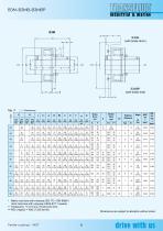
B3MB(with brake drum) it^ht II I ILrc B3MBP(with brake disk) Tab. 7 X>t> Dimensions • Metric max bore with a keyway ISO 773 - DIN 6885/1 (Inch max bore with a keyway USAS B17.1 square) Dimensions are subject to alteration without notice
Open the catalog to page 7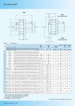
(with brake drum) (with brake disk) • Metric max bore with a keyway ISO 773 - DIN 6885/1 (Inch max bore with a keyway USAS B17.1 square) Dimensions are subject to alteration without notice
Open the catalog to page 8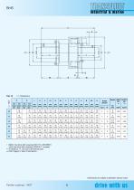
• Metric max bore with a keyway ISO 773 - DIN 6885/1 (Inch max bore with a keyway USAS B17.1 square) Dimensions are subject to alteration without notice
Open the catalog to page 9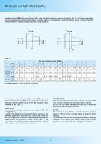
Flexible couplings BM series can withstand radial, axial, angular misalignment values according to Tab. 10; such values are just approximate because the coupling compensation capability depends on applied load and rotational speed values. It is recommended anyway to perform the best possible alignment during installation. *H nominal tolerance: + 1 /-0.5 mm (+0.04 / -0.02 inch) For operating rotational speed higher than 1800 rpm, it is recommended to reduce by 50% the max allowable misalignment. Maximum rotational speed cannot exceed the allowable values indicated on Tab. 1 pag. 3. All our flexible...
Open the catalog to page 10
• On request special nodular Iron EN-GJS-350-22 LT for low temperature -40°C (-40°F) •• On request special rubber 60°Sh(A) or 80°Sh(A) Tab. 12 - Screw tightening torque Size For max bore set screw should be placed at 90° from keyway - for type and dimensions see table TF5726 Tightening torque according to screw size and class, please refer to table N 1152 For dowel pin dimensions contact TRANSFLUID Tab. 13 - Rubber element type and quantity 01 Tab. 14 - Rubber element dimensions X»Type
Open the catalog to page 11
REVERMATIC 11-700 power shift with torque converter FLUID COUPLING K series FLUID COUPLING KX series DISC AND DRUM BRAKE TFDS-NBG series PNEUMATIC CLUTCH TP series TRANSFLUID BEIJING TRADE CO. LTD Beijing Ph.: +86.10.60442301-2 [email protected] TRANSFLUID FRANCE s.a.r.l. 38110 Rochetoirin Ph.: +33.9.75635310 [email protected] NORTH EUROPE TRANSFLUID B.V. (Bellmarine) NL- 3812 RB, Amersfoort Ph. +31 (0)85 4868530 [email protected] TRANSFLUID UK LTD London Ph. +44.7445501066 [email protected] TRANSFLUID LLC Auburn, GA 30011 Ph.: +1.770.822.1777 [email protected] Global web site:...
Open the catalog to page 12All Transfluid catalogs and technical brochures
 K - CK - CCK FLUID COUPLINGS
8 Pages
 KX FLUID COUPLINGS KX SERIES
4 Pages
 HYBRID & ELECTRIC TECHNOLOGY
16 Pages
 ELECTRIC PROPULSION SYSTEMS
28 Pages
 Batteries
4 Pages
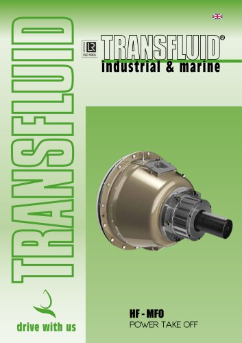 HF - MFO POWER TAKE OFF
8 Pages
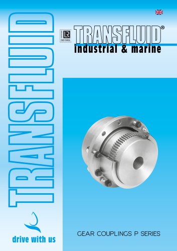 GEAR COUPLINGS P SERIES
12 Pages
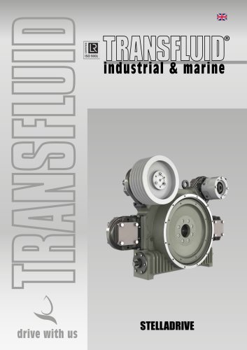 STELLADRIVE
8 Pages
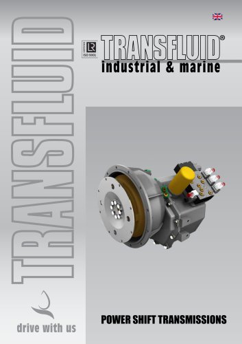 POWER SHIFT TRANSMISSIONS
8 Pages
 TPO-TPH
6 Pages
 SH-SHC OIL ACTUATED CLUTCHES
8 Pages
 SL SPRING LOADED BRAKES
4 Pages
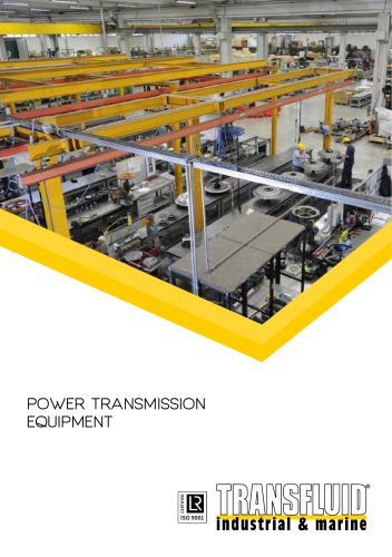 Production range
5 Pages
 Marine Transmissions brochure
16 Pages
 TowerClutch
8 Pages
 High Speed
8 Pages

- DC electromotor
- Synchronous motor
- Alternating current motor
- Asynchronous motor
- Electromotor for industrial applications
- Three-phase motor
- Compact electromotor
- High-efficiency electromotor
- Friction brake
- Permanent magnet motor
- Transfluid flange coupling
- Pack unit
- Torque coupling
- Spring brake
- Transmission coupling
- Electric hydraulic power unit
- Disc brake