Catalog excerpts

V-Cover INSTALLATION INSTRUCTION MANUAL
Open the catalog to page 1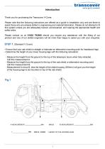
Thank you for purchasing the Transcover V-Cover. Please note that the following instructions are offered as a guide to installation only and are there to assist those who are already skilled in engineering and material fabrication. Please do not attempt to fit this system unless you are adequately trained, accompanied, and wearing the appropriate health and safety attire. Please contact us on 01622 792006 should you require any assistance with the fitting of our product and one of our skilled engineers will be more than happy to assist you with your enquiries. STEP 1. (Standard V Cover) •...
Open the catalog to page 2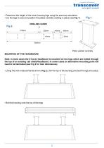
• Determine the height of the tower housing legs using the previous calculation. • Cut the legs to size and position the plates centrally welding in place (see Fig 1). Fig 1- Plate welded centrally MOUNTING OF THE HEADBOARD Note: In most cases the V-Cover headboard is mounted on two legs which are bolted through the top of an existing cab shield/headboard. In some cases an alternative mounting point will need to be fabricated (see Fig 2 for hole dimensions). • Using the hole measurements shown (Fig 2), drill the top of the housing and bolt the legs into place. • Bolt the housing onto the...
Open the catalog to page 3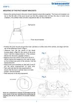
-transcover we've got it covered! STEP 2. MOUNTING OF THE PIVOT MOUNT BRACKETS • Secure the spring boxes to the pivot mount bracket using bolts supplied. The lower arm bracket is to be on the flat side of the pivot mount (so that the pressed side will face the skip in transit once installed.) The slotted holes will allow adjustment later on the installation. U If • Position the pivot mounts around the main cylinders on either side of the vehicle, and align with the top of the telescopic boom. (Fig 1). • Measure from the top centre of the sheet housing plate in Fig 2 to the centre of the...
Open the catalog to page 4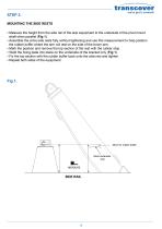
STEP 3. MOUNTING THE SIDE RESTS • Measure the height from the side rail of the skip equipment to the underside of the pivot mount shaft when parallel (Fig 1). • Assemble the arms side rests fully without tightening and use this measurement to help position the rubber buffer where the arm will rest on the side of the boom arm. • Mark the position and remove the top section of the rest with the rubber stop. • Weld the fixing plate into place on the underside of the bracket only (Fig 1). • Fix the top section with the rubber buffer back onto the side rest and tighten. • Repeat both sides of...
Open the catalog to page 5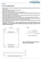
FITTING THE PRIMARY ARMS • To determine the primary arm length take the measurement that A and B arrived at from STEP 2 and deduct 35mm. • Check measurements once more as a precaution. • Cut two of the arms to this length. • Attach the two spacing sleeves onto the pivot mount shafts. • Attach the cut arms to the sleeved pivot mount shafts and lift both the attached arms individually and rest onto the rubber stops of the side rests. • Measure the widest point of the vehicle (this is normally the bolt heads at the top of the boom arms). Add 30mm for clearance, call this measurement ‘A’. •...
Open the catalog to page 6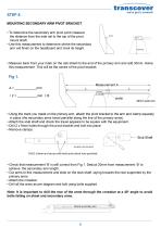
transcover we've got it covered! MOUNTING SECONDARY ARM PIVOT BRACKET • To determine the secondary arm pivot point measure the distance from the side rail to the top of the pivot mount shaft. • Use this measurement to determine where the secondary arm will finish on the headboard and mark its height • Measure back from your mark on the cab shield to the end of the primary arm and add 30mm. Halve this measurement. This will be the centre of the pivot bracket. ' Using the mark you made on the primary arm, attach the pivot bracket to the arm and clamp squarely in place (the secondary arms...
Open the catalog to page 7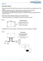
ELECTRICAL CIRCUIT • Mount the relay box to the rear of the cab sheild on the motor side of the housing leaving room for the switch. • Mount the waterproof switch in a protected position on the drivers side of the vehicle • Wire the relay box and waterproof switch as per the wiring diagram below. • Ensure all wires are fastened securely to the vehicle. Transcover recommend routing cables within protective conduit. Note: Position within 4 Meters of batteries in a dry, safe location. • Using a 5mm twist drill, drill 4 holes (Fig 1) and secure box with bolts provided. Mounting Relay Box Using...
Open the catalog to page 8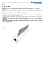
FITTING THE TARP • Keeping the vinyl wear patch downwards, slide the sheet onto the rollerbar (Fig 1) in the sheet housing. • Undo one side of the primary arm set, and lifting the secondary arm slide the pocket of the tarp onto the crossbar. • Re-attach the crossbar to the primary arm set and tighten bolts. • By hand lift the secondary arm over the boom so that it rests on the cab shield of the skip equipment. • Mount small buffers to support the secondary arm. • Wind in the sheet and check that the secondary arm sits neatly under the primary arm on the sheet housing • Ensure that the...
Open the catalog to page 9
OPERATING INSTRUCTIONS It is extremely important that the operators of our equipment are fully aware of how our products should be used. Please could you make sure that the driver is aware of this document and is fully capable and confident in the use of the product before leaving the premises. • Do a visual safety check of the load from ground level and ensure that you are wearing the appropriate safety wear. • Ensure that the appropriate stops are in place on the skip bed. • Dress the load from ground level and ensure that any sharp objects are moved so as not to catch the sheet. • (Tower...
Open the catalog to page 10All Transcover catalogs and technical brochures
-
T3T TrailerCover Installation
14 Pages
-
AgriCover
1 Pages
-
DoubleCover Manual
2 Pages
-
UnderCover brochure
4 Pages
-
HyCover product range brochure
18 Pages

