Series 350 Specs Gaging (LVDT) Transducers

Series 350 Specs Gaging (LVDT) Transducers
- Working Range: Varies from ±0.050 inches to ±3.00 inches depending on the model.
- Mechanical Travel: Ranges from 0.14 inches to 6.25 inches.
- Input Voltage: 6.0 VDC minimum to 28 VDC maximum.
- Output Voltage: Varies with input voltage, providing higher outputs at higher input voltages.
- Linearity: ±0.50% full scale over the total working range.
- Temperature Range: -65°F to +200°F (-54°C to +93°C).
- Mating connector assemblies and cable assemblies are available with specific part numbers.
- Options include reverse spring, special length interconnecting cable, vented housing for high pressure applications, and air purge port.
Catalog excerpts
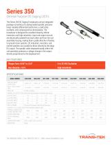
General Purpose DC Gaging LVDTs The Series 350 DC Gaging Transducers are an integrated package consisting of a spring loaded spindle, precision linear variable differential transformer, a solid state oscillator, and a phasesensitive demodulator. The transducer is designed for excellent linearity, infinite resolution, and high sensitivity. Input and output circuits are electrically isolated from each other and from the coil assembly housing, making them usable directly in floating or ground return systems. DC indicators, recorders, and control systems can usually be driven directly by the large DC output. The spindle, when displaced axially within the coil assembly, produces a voltage change in the output directly proportional to the displacement. KEY FEATURES Ranges from ±0.05” to ±3.0” High Sensitivity SPECIFICATIONS MODEL NUMBER WORKING RANGE ± Inches (mm) MECH. TRAVEL, Inches (mm) NOMINAL F.S. OUTPUT ±VDC (tested with load impedance simulating open circuit) @ 6 VOLT INPUT @ 28 VOLT INPUT INPUT CURRENT 6.3 mA @ 6 Volt input to 48 mA @ 28 Volt input LINEARITY % FULL SCALE OVER TOTAL WORKING RANGE ±0.50 INTERNAL CARRIER FREQ., Hz NOM. GREATER THAN: OUTPUT IMPEDANCE, Ohms TEMPERATURE RANGE
Open the catalog to page 1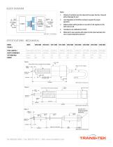
BLOCK DIAGRAM Polarity of excitation must be observed for proper function. Reversal will not damage the unit. Load Impedance of 50 KOhms minimum required for proper Output polarity will be positive on one side of null, negative on the other side of null. White lead is more positive with respect to the Green lead when the core is moved toward the lead end. SPECIFICATIONS - MECHANICAL 3IS-3I UNF-2ATHD (2 LOCKING NUTS SUPPLIED) Goto. 6 n. tl.aa rtaprtyiij
Open the catalog to page 2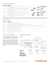
ACCESSORIES & OPTIONS
Open the catalog to page 3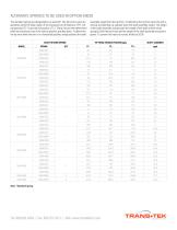
ALTERNATE SPRINGS TO BE USED IN OPTION X0038 assembly weight from the tip force. To determine the tip force when the unit is vertical, and pointing up, subtract twice the shaft assembly weight. The weight of the shaft assembly includes both the weight of the shaft and the return spring(s). Both the tip forces and the weight of the shaft assembly are given in grams. To convert this value to ounces, divide by 28.38. The standard springs are designated by an asterisk*. The tip force is given for operation within the linear region of the transducer at full extension (TF-), full compression (TF+),...
Open the catalog to page 4All TRANS-TEK catalogs and technical brochures
 Series 240
4 Pages
 Series 310-320
2 Pages
 Series 330
3 Pages
 Series 605
2 Pages
 Series 607 Specs
4 Pages
 Series 100
3 Pages
 Series 280
2 Pages
 Series 230
4 Pages
 Series 430
3 Pages
 Series P010 Specs
2 Pages
 Series D100 Specs
1 Page
 Series 1003 Specs
2 Pages
 Series 1000 Specs
2 Pages
 Series 605 Versatile ADTs
2 Pages


- Position transducer
- Displacement transducer
- Linear displacement sensor
- No-contact position sensor
- Analog displacement transducer
- Non-contact displacement sensor
- Metal position sensor
- Metal displacement sensor
- Angular position sensor
- LVDT displacement sensor
- Digital displacement sensor
- Rugged displacement sensor
- Absolute displacement sensor
- Angular displacement sensor
- Miniature displacement sensor
- Vibration velocity sensor
- Capacitive displacement sensor
- SSI displacement transducer
- Capacitive position sensor