Model 0607 360° Angular Displacement Transducer Model 1004 Meter/Counter Display

Model 0607 360° Angular Displacement Transducer Model 1004 Meter/Counter Display
- Encoder: Outputs 1800 cycles of quadrature TTL signal per revolution, with a zero reference pulse. It features a compact design, low weight, and can be mounted via servo or bolt-face. It offers 0.025° accuracy and 0.05° resolution.
- Display: A 5-digit LED panel mount display that decodes encoder output into 7200 counts/revolution. It provides latchable, parallel BCD output and can be used as an 8-bit parallel, word serial, multiplexed signal.
- Encoder: 5 VDC excitation, 3000 RPM max speed, 100 kHz frequency response, and operates in temperatures from -23°F to 158°F.
- Display: Operates with 5 VDC, accepts TTL level inputs, and provides a ±5.0 VDC analog output option.
Catalog excerpts

The Model 0607-0001 Optical Encoder and Model 1004- 0000 Counter Display system provides precision feedback and readout of shaft angular displacement over the full 360° revolution. From a fixed or user settable point, angular position is displayed in degrees over indefinite shaft revolutions at speeds up to 3000 RPM, with equivalent BCD output. In simplest mode, Encoder position is displayed in increments of 0.05° over the range 0.00° to 359.95°. Display and Encoder are sold separately and will deliver full accuracy without adjustment. Angular Displacement Transducer 360° Precision Feedback and Display Model 0607-0001 is a rotary, incremental Encoder that outputs 1800 cycles of quadrature TTL signal and one zero reference pulse (ZR) per shaft revolution. Compact size, low weight, and servo and/or bolt-face mounting make it easy to install, even where space is limited. The Encoder’s precision pilot diameter provides a reference for mounting the unit concentric to the shaft to be monitored. Four tapped holes in the face, or the servo slot on its circumference, provide two means for securing the body to the user’s reference surface. Installation of a flexible shaft coupling (see Accessories section, pg. 4) is highly recommended to protect the Encoder from excessive misalignment or motion of the monitored shaft. Encoder cable can be soldered directly to the Display connector or can be extended (see Accessories section, pg. 4). Model 0607-0001 Optical Encoder • Displays Full 360° Working Range • 0.025° Accuracy and 0.05° Resolution • Speeds to 3,000 RPM • Binary-Coded-Decimal (BCD) Output Model 1004-0000 is a panel mount, 5-digit LED Display that excites the Encoder, decodes its output into 7200 counts/revolution, and displays the shaft angle position - in increments of 0.05° - from the last reset. It also provides latchable, parallel BCD output that matches the displayed value. When tri-state enabled, the BCD output can be used as an 8-bit parallel, word serial, multiplexed signal for input into an 8-bit port. The compact 1/8 DIN case, rear-panel set-up, and solder termination make it easy to install, even where space is limited. The Display installs directly through panels up to 0.20 inch (5.1 mm) thick, or can be used as a benchtop instrument. All necessary mating edge-type connectors are included, to which Encoder leads, 5 VDC power and any other required connections can be soldered directly (see Accessories section for appropriate Line Powered Supplies, pg. 4). The base unit is available as Model 1004-00000. Unit with analog output option, providing ±5.0 VDC over the range ±359.95°, is available as Model 1004-00001. Model 1004-0000 Counter Display KEY FEATURES 1
Open the catalog to page 1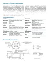
Encoder Specifications Electrical Mechanical 1800 cycles per revolution (7200 counts per revolution 10 lb axially and radially, maximum; Resolution Range with external 4X counting when using A and B Shaft Loading 100,000 radians/sec2 maximum angular channel outputs) acceleration Light Source LED Shaft Radial Runout 0.001 inch (.025mm) T.I.R. Light Sensor Photodiode Bearing R-4 shielded; 0.1 ounce-inch (7.2 gram-cm) maximum starting torque at 25°C Excitation 5 VDC ±10%, 80 mA Operating Speed 3000 RPM maximum continuous Two count channel outputs (A and B) in phase Output Format quadrature, plus...
Open the catalog to page 2
Upper Connector J-2 Pin # Function Pin# Function 1 A Analog Common 2 B Analog Out 3 Mode 1 On (F4) C DC Common 4 Reset to Zero (F1, Momentary) D DC Common 5 E 6 Z from Encoder F Z from Encoder (Not Used) 7 B from Encoder H B from Encoder (Not Used) 8 A from Encoder J A from Encoder (Not Used) 9 K +5 Volts to Encoder 10 L DC Common to Encoder 11 Direction (F3) M DC Common 12 A Quad B X1 N DC Common 13 A Quad B X2 P DC Common 14 Z On (F2) R DC Common 15 +5 Volts In S DC Common In Lower Connector J-1 Pin # Function Pin# Function 1 Digit 1, Bit 8 A Digit 1, Bit 4 2 Digit 1, Bit 1 B Digit 1, Bit 2...
Open the catalog to page 3
BORE .251 (6.38) .. .001 (.025) BOTH SIDES .078 (2.0) SOCKET HEAD SCREW – 4 PLCS. .27 (6.9) TYPICAL .50 (12.7) 1.00 (25.4) For applications with max. angular offset 5.., max. parallel offset .007 (.18), max. torque 71 ounce–inch (5130 g-cm) All Dimensions in Inches (mm) A: 2 (51) B: 2.2 (56) A: 3 (76) B: 2.6 (66) A: 1.6 (41) B: 1.4 (36) A, B = 58 (1473) Long Typical Output Cable A = Model 1100-0000, B = Model 1100-0001 All Dimensions in Inches (mm) Dimensional Diagram - Shaft Coupler Orders can be placed directly with Trans-Tek, Inc., or with any of our Sales Representatives. Orders may be placed...
Open the catalog to page 4All TRANS-TEK catalogs and technical brochures
 Series 240
4 Pages
 Series 310-320
2 Pages
 Series 330
3 Pages
 Series 605
2 Pages
 Series 607 Specs
4 Pages
 Series 100
3 Pages
 Series 280
2 Pages
 Series 230
4 Pages
 Series 430
3 Pages
 Series P010 Specs
2 Pages
 Series D100 Specs
1 Page
 Series 1003 Specs
2 Pages
 Series 1000 Specs
2 Pages
 Series 605 Versatile ADTs
2 Pages


- Position transducer
- Displacement transducer
- Linear displacement sensor
- No-contact position sensor
- Analog displacement transducer
- Non-contact displacement sensor
- Metal position sensor
- Metal displacement sensor
- Angular position sensor
- LVDT displacement sensor
- Digital displacement sensor
- Rugged displacement sensor
- Absolute displacement sensor
- Angular displacement sensor
- Miniature displacement sensor
- Vibration velocity sensor
- Capacitive displacement sensor
- SSI displacement transducer
- Capacitive position sensor