


- Company
- Products
- Catalogs
- News & Trends
- Exhibitions
UDL Series Complete Catalogue

UDL Series Complete Catalogue
This section provides an overview of the document, including measurement units, service factors, selection criteria, thermal power, and maintenance procedures. It highlights the importance of understanding the service factor (FS) for application qualification, considering load type, operation duration, and start frequency. The FS must be equal to or lower than the gear unit service factor Fs’.
Defines units such as radial and axial loads in Newtons, dimensions in millimeters, and power in kilowatts. Conversion factors are provided for different units.
The service factor (FS) is crucial for determining application type, considering load nature, operation hours per day, and start-ups per hour. FS values differ based on motor type, with specific multipliers for internal combustion engines and self-braking electric motors.
Details the calculation of input power (P’) based on required torque (T2) and transmission ratio. It includes guidelines for selecting gearboxes and gearmotors, considering factors like input speed and service factor.
Emphasizes checking radial and axial loads against admissible values. Allows for emergency overloads up to 100% of T2 torque during standard operation. Recommends torque limiting devices for frequent or higher overloads.
Discusses rated thermal power (Pt0) for different gearbox types, indicating maximum admissible power under continuous duty at 30°C ambient temperature. Pt0 values should be corrected with coefficients to reflect actual operating conditions.
The document outlines the importance of adjusting the thermal power values (Pt0) using specific coefficients to account for real operating conditions. These coefficients include the temperature coefficient (ft), ventilation coefficient (fv), and utilization coefficient (fu). The document provides tables for these coefficients based on ambient temperature and operational minutes per hour.
After selecting the gearbox, it is crucial to verify that the maximum output torque (T2Mmax) provided by the backstop device is sufficient for the application's needs. This involves checking the torque (T2NOM) required to ensure motion irreversibility and considering load factors (fc) for different operational conditions.
The document emphasizes the selection of appropriate lubricants based on operating and environmental conditions to ensure optimal gearbox performance. It discusses the importance of viscosity and additives in oils, recommending synthetic oils for their advantages in efficiency and stability.
Proper installation is crucial to eliminate vibrations and ensure alignment between the gearbox, motor, and driven machine. The document advises using flexible couplings and installing protective devices like overload cutouts and torque limiters to prevent damage from prolonged overloads or shocks.
- Table 3: Temperature coefficients (ft) based on ambient temperature.
- Table 4: Utilization coefficients (fu) based on operational minutes per hour.
- Table 5: Application factors (fa) based on insertions per hour and daily operating hours.
- Table 6: Temperature factors (ft) based on ambient temperature.
If the gearbox operates below 0°C, special configurations with tight chambers are recommended to enhance the backstop device's performance. For further assistance, contact the technical department.
The components to be fitted on the gear units must adhere to specific machining tolerances: SHAFT ISO h6 and HOLE ISO H7. This ensures proper alignment and functionality.
The gearbox should be mounted to eliminate vibrations, ensuring alignment with the motor and machine. Use elastic or self-aligning couplings where possible. If the gearbox is exposed to overloads, shocks, or blockage risks, install motor switches, torque limiters, or hydraulic couplings. Ensure radial and axial loads on drive and output shafts do not exceed permissible limits. Clean and lubricate surfaces before assembly to prevent seizure and oxidation. Use tie-rods and extractors for assembly, and protect oil seals during painting to maintain sealing properties. Verify lubricant levels and breather plug positions before operation, especially for outdoor installations.
Gradually increase transmitted power or limit the machine's resistant torque during the initial operating hours to ensure proper running-in of the gearbox.
For gear units lubricated with mineral oil, change the oil after the first 500-1000 operating hours and flush the gearbox if possible. Regularly check lubricant levels and change oil every 4000 hours. If synthetic oil is used, oil changes can occur every 12500 hours. In humid environments, fill the gearbox with oil when inactive and restore the correct oil level before reuse.
The mechanical variator uses an epicyclic transmission for variable ratios. The motor rotates solar rings, which in turn rotate satellites. The position of the rolling contact point affects output speed and torque. Speed adjustments should only be made while the variator is running to avoid damage.
The UDL series variators are lightweight due to aluminum housing, allowing easy application and transport. They support both foot and flange mounting, reducing stock levels and delivery times. The closed input flange prevents oil leaks, and the magnetic breather plug extends maintenance intervals. The variators operate noiselessly and vibration-free in both directions.
The UDL series is available in sizes 002, 005, and 010, with specific power, speed, and torque specifications. Recommended lubricants include various ATF Dexron fluids from different brands.
Mounting positions include B5, V1, and V3, with specific dimensions provided for each UDL size. A breather plug kit is available for certain mounting positions.
Catalog excerpts
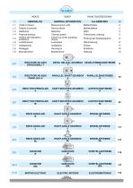
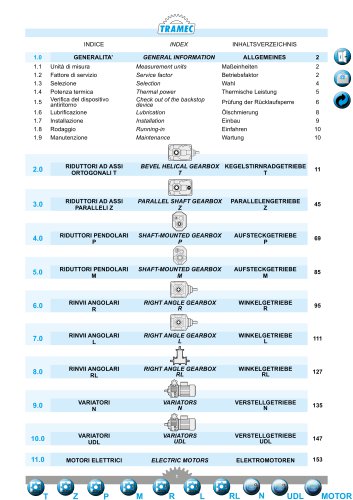
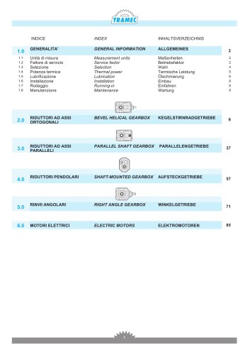
TRAMEC INDEX GENERALITA’ Unita di misura Fattore di servizio Selezione Potenza termica Verifica del dispositivo antiritorno Lubrificazione Installazione Rodaggio Manutenzione GENERAL INFORMATION Measurement units Service factor Selection Thermal power Check out of the backstop device Lubrication Installation Running-in Maintenance ALLGEMEINES MaGeinheiten Betriebsfaktor Wahl Thermische Leistung Prufung der Rucklaufsperre Olschmierung Einbau Einfahren Wartung 2.0 RIDUTTORI AD ASSI ORTOGONALI T BEVEL HELICAL GEARBOX KEGELSTIRNRADGETRIEBE T T RIDUTTORI AD ASSI PARALLELI Z PARALLEL SHAFT GEARBOX Z RIGHT ANGLE GEARBOX R RIGHT ANGLE GEARBOX L RIGHT ANGLE GEARBOX RL 0 MOTORI ELETTRICI ELECTRIC MOTORS
Open the catalog to page 1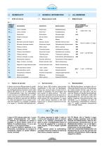
TRAMEC 1.0 GENERAL INFORMATION 1.1 Measurement units SIMBOLO SYMBOL SYMBOL UNITA’ DI MISURA MEASUREMENT UNIT MAftEINHEIT Carico Radiale Carico Assiale Dimensioni Fattore di servizio Massa Momento torcente riduttore Momento torcente motorid. Potenza motore Potenza corretta Potenza motoriduttore Potenza termica Potenza richiesta in uscita Rendimento dinamico Rapp. di trasm. nominale Rapporto di trasmissione reale Velocita albero entrata Velocita albero uscita Temperatura ambiente Rendimento Motori accoppiabili_ Radial load Axial load Dimensions Service factor Mass Gearbox torque Gearmotor torque Motor...
Open the catalog to page 2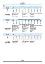
Classe di carico Load class Lastklasse Carico uniforme Uniform load Gleichmaeftig verteilte Last Classe di carico Load class Lastklasse APPLICAZIONI / APPLICATIONS / ANWENDUNGEN Agitatori per liquidi puri Alimentatori per fornaci Alimentatori a disco Filtri di lavaggio con aria Generatori Pompe centrifughe Pure liquid agitators Fournace feeders Disc feeders Air laundry filters Generators Centrifugal pumps Trasportatori con carico uniforme Uniform load conveyors Ruhrwerke fur reine Flussigkeiten Beschickungsvorrichtungen fur Brennofen Telleraufgeber Spulluftfilter Generatoren Kreiselpumpen Forderer...
Open the catalog to page 3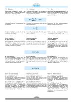
Determinare la potenza in entrata P’ (in Calculate input power P’ (on the basis of Bestimmen Sie die Antriebsleistung P’ (je base alla coppia T2 richiesta dall’applica- the torque T2 required by the application), nach dem bei der Anwendung erforderzione) con la seguente formula: using the following formula: lichen Drehmoment T2) mit Hilfe der folgenden Formel: Calcolare il rapporto di trasmissione con Calculate the transmission ratio with the Berechnen Sie das Untersetzungsverla relazione: following equation: hältnis mit Hilfe der Gleichung: Scegliere il fattore di servizio FS dell’ ap- Select...
Open the catalog to page 4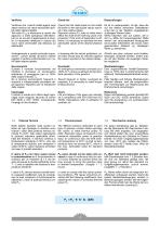
Verificare che i carichi radiali agenti sugli alberi rientrino nei valori ammissibili riportati nelle relative tabelle. Tali valori (FR2) si riferiscono a carichi che agiscono a metà sporgenza dell’albero, per cui se il punto di applicazione è diverso, è necessario effettuare il calcolo dei nuovi valori ammissibili alla distanza (y) desiderata. Check that the radial loads on the shafts fall within to the admissible values reported in the relative tables. Reported values (FR2 refer to loads which affect the shaft at the half-way point of its projection; if the point of application is different,...
Open the catalog to page 5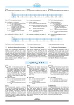
ft = coefficiente di temperature (v. tab. 3) ft = temperature coefficient (see table 3) ft = Temperaturkoeffizient (siehe Tabelle 3) Dove Dt sono i minuti di funzionamento in un'ora Dt is minutes of operation per hour 1.5 Check of back stop device 1.5 Verifica del dispositivo antiritorno Dopo aver correttamente selezionato il riduttore, occorre verificare se il valore del momento torcente T2M max garantito all’asse uscita del riduttore dal dispositivo antiritorno, considerate le reali condizio-ni di esercizio, e sufficiente a garantire il buon funzionamento dell’applicazione. Deve pertanto...
Open the catalog to page 6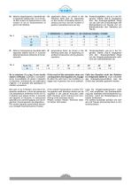
fa: fattore di applicazione, ricavabile dal-la seguente tabella (tab. 5) in funzio-ne del numero di inserzioni/ora e dal numero di ore di funzionamento al giorno del riduttore fa: application factor, as shown in the following table (tab. 5), depending on the number of backstop device insertions per hour and the number of gearbox operating hours per day. fa: Anwendungsfaktor, wie es in der fol-genden Tabelle (Tab.5) angegeben wird. Der Anwendungsfaktor hangt von der Zahl der Einschaltungen der Rucklaufsperre pro Stunde und von Betriebsstunden des Getriebes pro Tag ab. Temperaturfaktor, wie es...
Open the catalog to page 7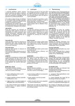
I cuscinetti dell’albero veloce vengono sempre lubrificati con grasso a base sintetica; altri cuscinetti vengono lubrificati solo se la posizione di montaggio non ne garantisce la corretta lubrificazione. The bearings mounted on the input shaft are supplied with grease, synthetic base; the other bearings are lubricated only if the mounting position does not assure a correct lubrication. Una scelta oculata del tipo di lubrificante, in funzione delle condizioni operative e ambientali, consente ai riduttori di raggiungere le prestazioni ottimali. Le prestazioni dei riduttori indicate nelle tabelle...
Open the catalog to page 8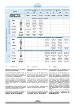
1.7 Installazione Montare il riduttore in modo tale da elimi-nare qualsiasi vibrazione. Curare particolarmente l'allineamento del riduttore con il motore e la macchina da comandare interponendo dove e possibi-le giunti elastici od autoallineanti. Quando il riduttore e sottoposto a sovrac-carichi prolungati, urti o pericoli di bloc-caggio, installare salvamotori, limitatori di coppia, giunti idraulici od altri dispositivi similari. Fare attenzione a non superare i valori consentiti di carico radiale ed assiale che agiscono sugli alberi veloce e lento. Assicurarsi che gli organi da montare sui riduttori...
Open the catalog to page 9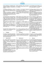
Prima di effettuare il montaggio pulire e Before assembling, clean and lubricate Vor der Montage sind die Flächen zu reilubrificare le superfici al fine di evitare il the surfaces to prevent seizure and con- nigen und zu schmieren, um Festfressen pericolo di grippaggio e l’ossidazione da tact oxidation. bzw. Kontaktoxidation zu vermeiden. contatto. Il montaggio va effettuato con l’ausilio di tiranti ed estrattori utilizzando il foro filettato posto in testa alle estremità degli alberi. Durante la verniciatura si consiglia di protteggere il bordo esterno degli anelli di tenuta per evitare che...
Open the catalog to page 10All TRAMEC catalogs and technical brochures
 GHA LINE
110 Pages
 ATEX Explosive Atmospheres
106 Pages
 Precision planetary gearboxes
146 Pages
 Worm gearboxes
170 Pages
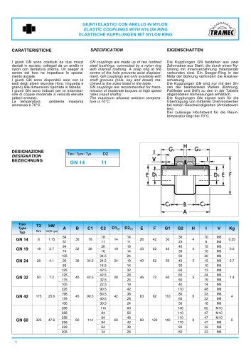
 COUPLINGS GN
1 Page
 ATEX cat.3 catalogue
35 Pages
 ATEX cat.2 catalogue
36 Pages
 Motors/Drive Stepless
6 Pages
 Motors/Drive Brushless
12 Pages
 Inverter IS7
5 Pages
 Inverter IC5
3 Pages
 Inverter IP5A
4 Pages
 Inverter IG5A
5 Pages
 Inverter IE5
3 Pages
 BCFK - BCRK Series
20 Pages
 SCFK - SCRK Series
20 Pages
 BFK - BRK Serie
18 Pages
 SFK - SRK Series
18 Pages
 TLS Line Catalogue
96 Pages
 Worm gearboxes catalogue
144 Pages
 Motion & Control
69 Pages
 CI3050
2 Pages
 VM Series complete catalogue
24 Pages
 H Series complete catalogue
36 Pages
 K Series complete catalogue
36 Pages
 X Series complete catalogue
40 Pages
 EP series complete catalogue
30 Pages
 REP series complete catalogue
32 Pages
 N Series Complete Catalogue
22 Pages
 L Series Complete Catalogue
26 Pages
 R Series Complete Catalogue
26 Pages
 M Series Complete Catalogue
20 Pages
 P Series Complete Catalogue
26 Pages
 Z Series Complete Catalogue
34 Pages
 T Series Complete Catalogue
44 Pages
 2 SFK - SRK
18 Pages
 BRUSHLESS DRIVE
12 Pages
 Motoinverter
6 Pages
 Planetary gearboxes catalogue
52 Pages
 GN series catalogue
1 Page
 RL series catalogue
18 Pages
 TLS series catalogue
96 Pages


Archived catalogs
 General catalogue (EN, DE, IT)
88 Pages

- DC electromotor
- Synchronous motor
- Alternating current motor
- Multipole motor
- Asynchronous motor
- Planetary gearbox
- Coaxial gearhead
- EC motor
- Electromotor for industrial applications
- Three-phase motor
- Precision gearhead
- Right angle gearhead
- Compact gearhead
- 4-pole motor
- Solid-shaft gearhead
- 2-pole motor
- IP55 motor
- Hollow-shaft gearhead