


- Company
- Products
- Catalogs
- News & Trends
- Exhibitions
REP series complete catalogue

REP series complete catalogue
The document provides comprehensive technical specifications for the REP and EP series of planetary gearboxes, detailing models such as REP 075, 100, 125, 150, and EP 55, 75, 90, 120, 155. It includes information on steps, nominal and maximum input speeds, torque values, and other mechanical properties.
This section explains the symbols and measurement units used, such as nominal ratio (i), moment of inertia (J), and rated output radial load (FR2).
- Characteristics: Designed for applications like machine tools, woodworking, and automation, offering four sizes with multiple reduction stages and output shaft types.
- Designation: Details on designating gearboxes based on size, steps, and parameters.
- Selection: Guidelines for selecting gearboxes based on duty cycles.
- Technical Data: Tables with technical specifications for each model.
Similar to the REP series, this section provides technical data and specifications for different models, focusing on industrial applications.
Includes additional technical details and explanations of terms used in the document.
Outlines duty coefficients for gearboxes, focusing on intermittent and continuous duty operations. Key parameters include maximum acceleration torque (T2A), rated intermittent allowable torque (T2N), and others.
Specifies equations for verifying relationships between torques and speeds for intermittent and continuous duty.
Provides tables for calculating cycle factors and utilization factors, including thermal capacity limits for power and torque.
Emphasizes temperature checks to prevent overheating and guidelines for calculating maximum operation duration.
Includes thermal capacity limits, loadless friction power, and loss of heat coefficients for different gearbox sizes.
Ensures maximum input speed does not exceed limits and provides guidelines for calculating average torque and speed.
Details specifications for output shafts, input flanges, and gearboxes, including dimensions, torque ratings, and speed limits.
Provides detailed steps for motor mounting, ensuring proper alignment and securing components.
Includes tables with reduction ratios, torque values, and performance data for different gearbox stages.
Advises removing the flange from the gearbox before motor mounting.
- Loosen fastening screws of the clamp.
- Remove the key from the motor shaft.
- Remove the flange from the gearbox.
- Clean contact surfaces.
- Fix the flange on the motor.
- Avoid impacts while fitting the motor.
- Tighten assembly screws alternately.
- Fix the clamp towards the motor and tighten according to timing.
- Tighten clamp screws according to specified torque.
- All screws are supplied according to strength class 12.9.
- Various screw diameters and setting torques are specified.
- Sliding Carriage: Linear motion using a chain with a reduction ratio of 1, calculating total torque for motor selection.
- Revolving Table: Rotation of a cylindrical table, using inertia torque to determine motor requirements.
- Calculation of inertia and its relation to torque and angular acceleration.
- Relations between input/output torque, power, efficiency, and reduction ratio.
- Warranty for manufacturing defects lasts one year from invoicing date.
- TRAMEC will replace or repair defective parts but not cover additional charges.
- Warranty void if instructions are not followed or unauthorized repairs are made.
- Returned goods accepted only if delivered free of charge.
This document is a technical catalogue that supersedes previous editions and reserves the right to modifications without notice.
- 06/2011: Change in height of EP 75.
- 01/2012: Decrease in angular backlash for EP.
- 03/2014: Modifications to dimensions of PAM REP 75 and C1 - EP120.
- 04/2015: Addition of PAM REP and PAM EP.
Catalog excerpts

ITRAMEC INHALTSVERZEICHNIS Dati tecnici REP Dati tecnici EP Simbologia REP Technical data EP Technical data Measurement units 1.0 RIDUTTORI EPICICLOIDALI PLANETARY GEARBOXES SERIE REP REP SERIES 2.0 RIDUTTORI EPICICLOIDALI PLANETARY GEARBOXES SERIE EP EP SERIES
Open the catalog to page 1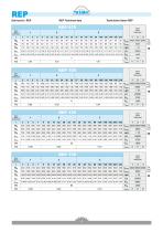
REP Technical data Technische Daten REP
Open the catalog to page 2
EP EP Technical data Technische Daten EP
Open the catalog to page 3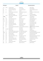
Symbols ITRAMEC Verwendete Symbole [arcmin] Gioco angolare standard — Coefficiente di dispersione termica [N] Carico assiale in uscita [N] a SOOmin-1 [N] Carico radiale nominale in uscita [N] a SOOmin"1 — Rapporto di riduzione nominale [kg.cm2] Momento d'inerzia riferito all'albero entrata [min-1] Velocita massima in entrata [min-1] Velocita nominale in entrata [min-1] Velocita media in ingresso [min-1] Velocita di rotazione media in uscita [min-1] Velocita di rotazione nominale in uscita [W] Potenza persa a vuoto [W] Potenza persa proporzionale alla potenza...
Open the catalog to page 4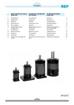
REP PLANETARY GEARBOXES REP SERIES Characteristics Designation Selection Temperature check Backlash Radial and axial loads on output shaft Lubrication Moments of inertia Technical data Dimensions Instructions for the motor assembling a 0 RIDUTTORI EPICICLOIDALI 1-0 SERIE REP 1.1 Caratteristiche 1.6 Carichi radiali e assiali 1.11 Istruzioni per il montaggio del motore
Open the catalog to page 5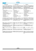
1.1 Caratteristiche La serie di riduttori epicicloidali REP e il risultato di un ottimo rapporto tra econo-micita del prezzo e garanzia di precisione delle caratteristiche di funzionamento. I nostri riduttori sono stati realizzati per un utilizzo prevalente sulle seguenti applica-zioni: • Macchine utensili • Macchine per la lavorazione del legno • Linee transfer • Macchine da stampa • Macchine automatiche per confe-zionamento ed imballaggio • Automazioni • Manipolatori • Macchine serigrafiche • Guide lineari La gamma dei riduttori REP e costituita da 4 grandezze (075, 100, 125 e 150), a 1, 2...
Open the catalog to page 6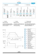
1.3 Selezione Verifica meccanica La selezione dei riduttori epicicloidali REP deve essere effettuata valutando se il servizio e intermittente o continuo. Noto il ciclo di lavoro: 1.3 Selection Mechanical check The selection of the REP planetary gearbox depends on whether the duty is continuous or intermittent. The working cycle being: Mechanische Prufung Bei der Wahl des REP Planetengetriebes soll es berucksichtigt werden, ob es um Aussetz- oder Dauerbetrieb handelt. Bei bekannten Arbeitszyklus:
Open the catalog to page 7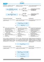
REP si definiscono i coefficient di utilizzo KU, KM secondo le seguenti formule: calculate KU, KM duty coefficients with the following formulae: darf der Anwendungskoeffizient KU, KM wie folgt kalkuliert werden: KU < 60% el and/und KM < 20 min Funzionamento intermittente S5 Intermittent duty Aussetzbetrieb KU > 60% o/ ori Oder KM £ 20 min Funzionamento continuo S1 Continuous duty Dauerbetrieb Funzionamento intermittente Intermittent duty Aussetzbetrieb In questo caso, deve essere verificata la In case of intermittent duty, the following Bei Aussetzbetrieb soll die folgende Rela-seguente...
Open the catalog to page 8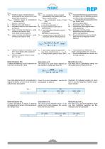
REP Dove : T2a = massima coppia di accelerazione in uscita garantita dal riduttore [Nm] (vedi tabelle delle prestazioni) T1amoT = massima coppia di accelerazione del motore [Nm] i = rapporto di riduzione fc = fattore di ciclo (vedi tabella 1) Rd = rendimento dinamico (vedi tabella delle prestazioni) T2n = coppia nominale intermittente in uscita ammessa dal riduttore [Nm] (vedi tabelle delle prestazioni) T2e = coppia nominale intermittente in uscita ammessa dal riduttore [Nm] Where: T2a = max. acceleration torque at output guaranteed by the gearbox [Nm] (see tables of performance) T1amoT = max....
Open the catalog to page 9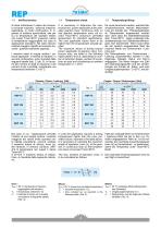
1.4 Verifica termica Si deve individuare il valore del momen-to torcente massimo / potenza massima, applicabile, in modo continuativo, in in-gresso al riduttore epicicloidale, tale per cui la temperatura del riduttore stesso non superi Tmax=95°C (massimo valore di temperatura raggiungibile nel caso di applicazioni standard). Tali valori devono risultare maggiori rispetto al momento torcente / potenza realmente applicati. I massimi valori di coppia motrice / potenza applicabili in entrata al riduttore, in servizio continuativo, sono ricavabili dalle seguenti tabelle (tab. 2, tab. 3), in funzio-ne...
Open the catalog to page 10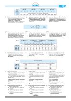
TS = temperatura massima (°C) alla quale il TS riduttore tendera a stabilizzarsi nel caso in cui sia applicata in ingresso la potenza P1, in condizioni di funzionamento continuo. Il valore di TS e ricavabile dalla seguente formula: = maximum temperature (°C) at which Ts the gearbox will tend to stabilize in case P1 power is applied at input, continuous duty. Calculate Ts value with the following formula: maximale Temperatur (C°), auf die das Getriebe sich stabilisieren wird, falls im Dauerbetrieb P1 Antriebsleistung an-gewendet wird. Ts ist mit der folgenden Formel zu berechnen: [°C] in cui:...
Open the catalog to page 11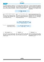
REP P1 e la potenza applicata in ingresso, da esprimersi in W. Nel caso in cui sia invece nota la coppia motrice applicata in ingresso T1, in Nm, si ricava il corrispondente valore di potenza, attraverso la relazione: P1 is the power applied at gearbox input and is expressed in W. In case one only knows T1 (driving torque applied at input) expressed in Nm, the corresponding power value can be obtained as follows: P1 ist die am Getriebeantrieb angewand-te Leistung und wird in W ausgedruckt. Falls nur T1 (Antriebsdrehmoment in Nm) bekannt ist, dann ist den entsprechenden Leistungswert mit der folgenden...
Open the catalog to page 12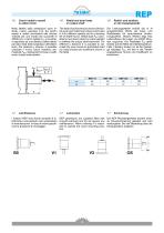
1.6 Carichi radiali e assiali su albero lento Nella tabella delle prestazioni sono in-dicati i valori, espressi in N, dei carichi assiali e radiali ammissibili alle diverse velocita per una durata dei cuscinetti di 20000 ore. Il carico radiale FR2 si conside-ra applicato ad una distanza dalla battuta pari alla meta della lunghezza dell'albero lento. Per distanze y diverse, e possibile calcolare il nuovo carico massimo am-missibile FR2Y utilizzando formula e coeffi-cienti indicati nella tabella. 1.6 Radial and axial loads on output shaft The table of performances shows admissible axial and radial...
Open the catalog to page 13All TRAMEC catalogs and technical brochures
 GHA LINE
110 Pages
 ATEX Explosive Atmospheres
106 Pages
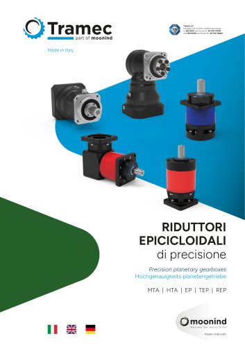 Precision planetary gearboxes
146 Pages
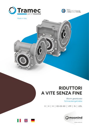 Worm gearboxes
170 Pages
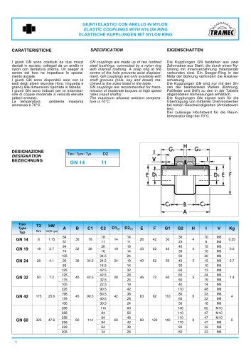
 COUPLINGS GN
1 Page
 ATEX cat.3 catalogue
35 Pages
 ATEX cat.2 catalogue
36 Pages
 Motors/Drive Stepless
6 Pages
 Motors/Drive Brushless
12 Pages
 Inverter IS7
5 Pages
 Inverter IC5
3 Pages
 Inverter IP5A
4 Pages
 Inverter IG5A
5 Pages
 Inverter IE5
3 Pages
 BCFK - BCRK Series
20 Pages
 SCFK - SCRK Series
20 Pages
 BFK - BRK Serie
18 Pages
 SFK - SRK Series
18 Pages
 TLS Line Catalogue
96 Pages
 Worm gearboxes catalogue
144 Pages
 Motion & Control
69 Pages
 CI3050
2 Pages
 VM Series complete catalogue
24 Pages
 H Series complete catalogue
36 Pages
 K Series complete catalogue
36 Pages
 X Series complete catalogue
40 Pages
 EP series complete catalogue
30 Pages
 UDL Series Complete Catalogue
16 Pages
 N Series Complete Catalogue
22 Pages
 L Series Complete Catalogue
26 Pages
 R Series Complete Catalogue
26 Pages
 M Series Complete Catalogue
20 Pages
 P Series Complete Catalogue
26 Pages
 Z Series Complete Catalogue
34 Pages
 T Series Complete Catalogue
44 Pages
 2 SFK - SRK
18 Pages
 BRUSHLESS DRIVE
12 Pages
 Motoinverter
6 Pages
 Planetary gearboxes catalogue
52 Pages
 GN series catalogue
1 Page
 RL series catalogue
18 Pages
 TLS series catalogue
96 Pages


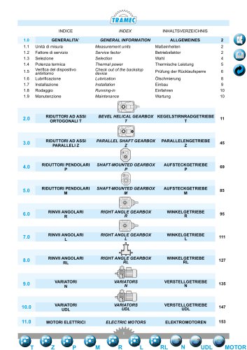
Archived catalogs
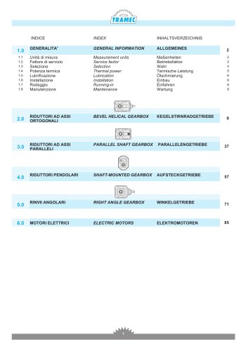 General catalogue (EN, DE, IT)
88 Pages

- Electromotor
- DC electromotor
- Synchronous motor
- Alternating current motor
- Multipole motor
- Asynchronous motor
- Planetary gearbox
- Coaxial gearhead
- EC motor
- Electromotor for industrial applications
- Three-phase motor
- Precision gearhead
- Right angle gearhead
- Compact gearhead
- 4-pole motor
- Solid-shaft gearhead
- 2-pole motor
- IP55 motor
- Hollow-shaft gearhead
- Flexible coupling