


- Company
- Products
- Catalogs
- News & Trends
- Exhibitions
EP series complete catalogue

EP series complete catalogue
The document provides comprehensive technical specifications for the REP and EP series of planetary gearboxes, covering models such as REP 075, REP 100, REP 125, REP 150, and EP 55, EP 75, EP 90, EP 120, EP 155. Key parameters include nominal and maximum input speeds, rated and maximum output torques, inertia, and noise levels.
1.0 Planetary Gearboxes REP Series
This section details the REP series, including steps, ratios, and torque specifications for different models. It features tables with values for nominal torque (T2N), maximum acceleration torque (T2A), and maximum emergency torque (T2S).
2.0 Planetary Gearboxes EP Series
The EP series is described with its characteristics and applications in machine tools, woodworking, and automation. It is available in five sizes with various output shaft and flange types. Technical data and dimensions are provided, along with motor assembly instructions.
3.0 Appendix
This section likely contains additional technical details and supplementary information.
Symbols and Units
The document includes a section on measurement units and symbols used throughout, such as nominal ratio (i), moment of inertia (J), and bearing life (Lh).
Key Specifications and Parameters
- Nominal Input Speed (n1nom): Ranges from 3000 to 5000 min-1 depending on the model.
- Maximum Input Speed (n1max): Up to 6000 min-1.
- Rated Output Torque (T2N): Varies by model, with values provided for different steps and ratios.
- Maximum Emergency Torque (T2S): Indicates the highest torque the gearbox can handle in emergency situations.
- Noise Level (LpA): Less than 70 dB(A) at 3000 min-1.
- Bearing Life (Lh): Estimated at 20,000 hours.
Design and Construction
The gearboxes are constructed with high-quality materials, including nitrided steel for housing, aluminum for flanges, and alloy steel for shafts and gears. Bearings are designed for long life and quiet operation.
Applications
The gearboxes are suitable for various applications, including machine tools, woodworking, printing, packaging, automation, and more.
Radial and Axial Loads on Slow Shafts
Specifications for permissible axial and radial loads on slow shafts are provided, expressed in Newtons (N), for different speeds and a bearing life of 20,000 hours. The radial load FR2 is considered at a distance equal to half the length of the slow shaft. For different distances, the new maximum permissible load FR2Y can be calculated using a formula and coefficients provided in a table.
Lubrication
EP gearboxes are supplied with long-life lubricant and are maintenance-free. It is important to specify the exact mounting position when ordering.
Symbols and Units of Measure
The document lists various symbols and their corresponding units of measure, such as nominal reduction ratio, nominal input speed, maximum input speed, intermittent output torque, maximum acceleration output torque, maximum emergency output torque, noise level, dynamic efficiency, bearing life, nominal output radial load, output axial load, torsional stiffness, standard backlash, and moment of inertia.
Moment of Inertia
The moment of inertia values are provided for different EP models (EP 55, EP 75, EP 90, EP 120, EP 155) and refer to the input shaft. The values are given for various stages and steps.
Technical Data and Dimensions
The document includes technical data and dimensions for various EP models, detailing general and output dimensions, input dimensions, and flange specifications. It also provides information on the necessary steps for mounting the motor, including the removal of the flange from the gearbox.
Technical Specifications
The document provides detailed technical specifications for various components, identified by codes such as P15, P16, etc. Each component is described with numerical values representing dimensions, capacities, and other technical parameters.
Procedures
Before mounting the motor, it is necessary to remove the flange from the gearbox. This is a critical step outlined in the assembly instructions.
Recommendations
For optimal assembly and operation, follow the specified procedures and refer to the detailed diagrams and tables provided in the document. Ensure all components are measured and installed according to the outlined specifications to maintain performance and safety standards.
Key Tables and Diagrams
The document contains numerous tables and diagrams that illustrate the dimensions and technical data of the components. These visual aids are essential for accurate assembly and understanding of the technical specifications.
Instructions for Motor Assembly
The document provides detailed instructions for the assembly of a motor onto a gearbox. Key steps include loosening the fastening screw of the clamp, removing the key from the motor shaft, cleaning contact surfaces, and ensuring the motor is fitted without impacts. The assembly screws should be tightened alternately, and the clamp screws should be tightened according to the specified torque values. All screws are supplied with a strength class of 12.9.
Application Examples
The document includes examples of applications such as the linear motion of a sliding carriage and the rotation of a revolving table. For the sliding carriage, calculations are provided for resisting torque and inertia torque, with a total torque requirement of 55 Nm. For the revolving table, the focus is on the moment of inertia and angular acceleration, with the torque requirement determined by these factors.
Formulary
The formulary section outlines the calculation of inertia and fundamental relations between torque, inertia, and angular acceleration. It also covers the relations between input and output torque and power, efficiency, and gearbox reduction ratio.
Warranty Conditions
The warranty for manufacturing defects lasts one year from the invoicing date. TRAMEC will replace or repair defective parts but will not cover additional charges for direct or indirect damages. The warranty is void if instructions are not followed or unauthorized repairs are made.
General Conditions
This catalogue supersedes all previous editions. All data listed are approximate and non-binding. The seller reserves the right to make changes without prior notice.
Revisions
- 06/2011: Change in EP 75 height
- 01/2012: Decreased angular backlash EP
- 03/2014: Modified dimensions for PAM REP 75 and C1 - EP120
- 04/2015: Added PAM REP and PAM EP
Catalog excerpts
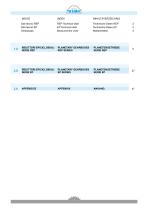
ITRAMEC INHALTSVERZEICHNIS Dati tecnici REP Dati tecnici EP Simbologia REP Technical data EP Technical data Measurement units 1.0 RIDUTTORI EPICICLOIDALI PLANETARY GEARBOXES SERIE REP REP SERIES 2.0 RIDUTTORI EPICICLOIDALI PLANETARY GEARBOXES SERIE EP EP SERIES
Open the catalog to page 1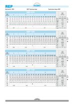
REP Technical data Technische Daten REP
Open the catalog to page 2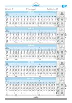
EP EP Technical data Technische Daten EP
Open the catalog to page 3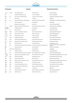
Symbols ITRAMEC Verwendete Symbole [arcmin] Gioco angolare standard — Coefficiente di dispersione termica [N] Carico assiale in uscita [N] a SOOmin-1 [N] Carico radiale nominale in uscita [N] a SOOmin"1 — Rapporto di riduzione nominale [kg.cm2] Momento d'inerzia riferito all'albero entrata [min-1] Velocita massima in entrata [min-1] Velocita nominale in entrata [min-1] Velocita media in ingresso [min-1] Velocita di rotazione media in uscita [min-1] Velocita di rotazione nominale in uscita [W] Potenza persa a vuoto [W] Potenza persa proporzionale alla potenza...
Open the catalog to page 4
EP PLANETARY GEARBOXES EP SERIES Characteristics Designation Selection Backlash Radial and axial loads on output shaft Lubrication Moment of inertia Technical data Dimensions Instructions for the motor assembling 2 0 RIDUTTORI EPICICLOIDALI 2-0 SERIE EP 2.1 Caratteristiche 2.5 Carichi radiali e assiali su albero lento
Open the catalog to page 5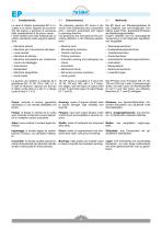
2.1 Caratteristiche La serie di riduttori epicicloidali EP e il ri-sultato di un ottimo rapporto tra economi-cita del prezzo e garanzia di precisione delle caratteristiche di funziona- mento. I nostri riduttori sono stati realizzati per un utilizzo prevalente sulle seguenti applica-zioni: • Macchine utensili • Macchine per la lavorazione del legno • Linee transfer • Macchine da stampa • Macchine automatiche per confeziona-mento ed imballaggio • Automazioni • Manipolatori • Macchine serigrafiche • Guide lineari La gamma dei riduttori e costituita da 5 grandezze (55, 75, 90, 120 e 155), a 1 e 2...
Open the catalog to page 6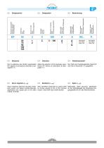
Numero di stadi Steps Untersetzungsstufen Coassiale Coaxial Koaxial Rapporto di riduzione Ratio Untersetzungsverhältnis Albero uscita Ouput shaft Durchmesser Abtriebswelle Flangia uscita Output flange Ausgangsflansch Albero entrata Input shaft Durchmesser Eingangswelle Flangia in entrata Input flange Eingangsflansch Grandezza Size Größe Riduttore epicicloidale Planetary gearbox Planetengetriebe Vedi tabelle See tables Siehe Tab. Vedi tabelle See tables Siehe Tab. Per la selezione dei riduttori epicicloidali Make the selection of the planetary gear- Die Wahl der Planetengetriebe Serie EP EP, seguire...
Open the catalog to page 7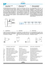
2.5 Carichi radiali e assiali su albero lento Nella tabella delle prestazioni sono indica-ti i valori, espressi in N, dei carichi assiali e radiali ammissibili alle diverse velocita per una durata dei cuscinetti di 20.000 ore. Il carico radiale FR2 si considera ap-plicato ad una distanza dalla battuta pari alla meta della lunghezza dell'albero lento. Per distanze y diverse, e possibile cal-colare il nuovo carico massimo ammissi-bile FR2Y utilizzando formula e coefficienti indicati nella tabella. 2.5 Radial and axial loads on output shaft The table of performances shows admissible axial and radial...
Open the catalog to page 8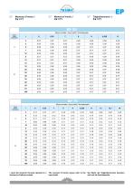
I valori dei momenti d'inerzia riportati si ri- The moment of inertia values refer to the Die Werte der Tragheitsmoment beziehen feriscono all'albero entrata. input shaft. sich auf die Antriebswelle.
Open the catalog to page 9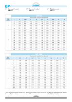
I valori dei momenti d'inerzia riportati si ri- The moment of inertia values refer to the Die Werte der Tragheitsmoment beziehen feriscono all'albero entrata. input shaft. sich auf die Antriebswelle.
Open the catalog to page 10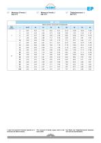
I valori dei momenti d'inerzia riportati si ri-feriscono all'albero entrata. The moment of inertia values refer to the input shaft. Die Werte der Tragheitsmoment beziehen sich auf die Antriebswelle.
Open the catalog to page 11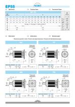
Stadi / Steps / Stufenzahl
Open the catalog to page 12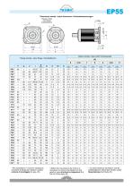
EP55 Dimensioni entrate / Input dimensions / Antriebsabmessungen Flangia entrata Input flange Flange entrata / Input flange / Antriebsflansch * Per assemblare il motore e necessario smontare la flangia dal riduttore (vedere schema di montaggio 2 a pag. 45). * Before the mounting of the motor it is necessary to remove the flange from the gearbox (see structural arrangement 2 at the top of the page 45). * Vor dem Einbauen des Motors soll die Getriebeflansch abmontiert werden (siehe Bauanleitung 2 auf Seite 45).
Open the catalog to page 13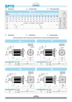
2.8 Dati tecnici 2.8 Technical data 2.8 Technische Daten Dimensioni generali e uscite / General and output dimensions / General-und Abtriebsabmessungen AA Stadi / Steps / Stufenzahl Stadi / Steps / Stufenzahl Stadi / Steps / Stufenzahl Stadi / Steps / Stufenzahl
Open the catalog to page 14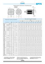
EP75 Dimensioni entrate / Input dimensions / Antriebsabmessungen Flange entrata / Input flange / Antriebsflansch * Per assemblare il motore e necessario smontare la flangia dal riduttore (vedere schema di montaggio 2 a pag. 45). * Before the mounting of the motor it is necessary to remove the flange from the gearbox (see structural arrangement 2 at the top of the page 45). * Vor dem Einbauen des Motors soll die Getriebeflansch abmontiert werden (siehe Bauanleitung 2 auf Seite 45).
Open the catalog to page 15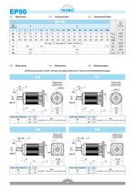
Dimensioni generali e uscite / General and output dimensions / General-und Abtriebsabmessungen Stadi / Steps / Stufenzahl Stadi / Steps / Stufenzahl Stadi / Steps / Stufenzahl Stadi / Steps / Stufenzahl
Open the catalog to page 16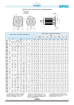
EP90 Dimensioni entrate / Input dimensions / AntriebsabmessungenLmax Flange entrata / Input flange / Antriebsflansch * Before the mounting of the motor it is necessary to remove the flange from the gearbox (see structural arrangement 2 at the top of the page 45).
Open the catalog to page 17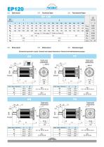
2.9 Dimensioni 2.9 Dimensions 2.9 Abmessungen Dimensioni generali e uscite / General and output dimensions / General-und Abtriebsabmessungen Stadi / Steps / Stufenzahl TQ Stadi / Steps / Stufenzahl Stadi / Steps / Stufenzahl
Open the catalog to page 18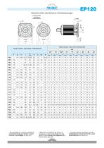
EP120 Dimensioni entrate / Input dimensions / Antriebsabmessungen Flange entrata / Input flange / Antriebsflansch * Before the mounting of the motor it is necessary to remove the flange from the gearbox (see structural arrangement 2 at the top of the page 45). Per assemblare il motore e necessario smontare la flangia dal riduttore (vedere schema di montaggio 2 a pag. 45).
Open the catalog to page 19All TRAMEC catalogs and technical brochures
 GHA LINE
110 Pages
 ATEX Explosive Atmospheres
106 Pages
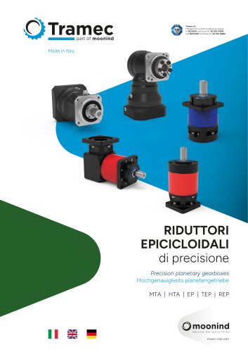 Precision planetary gearboxes
146 Pages
 Worm gearboxes
170 Pages
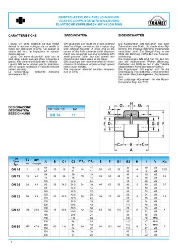
 COUPLINGS GN
1 Page
 ATEX cat.3 catalogue
35 Pages
 ATEX cat.2 catalogue
36 Pages
 Motors/Drive Stepless
6 Pages
 Motors/Drive Brushless
12 Pages
 Inverter IS7
5 Pages
 Inverter IC5
3 Pages
 Inverter IP5A
4 Pages
 Inverter IG5A
5 Pages
 Inverter IE5
3 Pages
 BCFK - BCRK Series
20 Pages
 SCFK - SCRK Series
20 Pages
 BFK - BRK Serie
18 Pages
 SFK - SRK Series
18 Pages
 TLS Line Catalogue
96 Pages
 Worm gearboxes catalogue
144 Pages
 Motion & Control
69 Pages
 CI3050
2 Pages
 VM Series complete catalogue
24 Pages
 H Series complete catalogue
36 Pages
 K Series complete catalogue
36 Pages
 X Series complete catalogue
40 Pages
 REP series complete catalogue
32 Pages
 UDL Series Complete Catalogue
16 Pages
 N Series Complete Catalogue
22 Pages
 L Series Complete Catalogue
26 Pages
 R Series Complete Catalogue
26 Pages
 M Series Complete Catalogue
20 Pages
 P Series Complete Catalogue
26 Pages
 Z Series Complete Catalogue
34 Pages
 T Series Complete Catalogue
44 Pages
 2 SFK - SRK
18 Pages
 BRUSHLESS DRIVE
12 Pages
 Motoinverter
6 Pages
 Planetary gearboxes catalogue
52 Pages
 GN series catalogue
1 Page
 RL series catalogue
18 Pages
 TLS series catalogue
96 Pages



Archived catalogs
 General catalogue (EN, DE, IT)
88 Pages

- Electromotor
- DC electromotor
- Synchronous motor
- Alternating current motor
- Multipole motor
- Asynchronous motor
- Planetary gearbox
- Coaxial gearhead
- EC motor
- Electromotor for industrial applications
- Three-phase motor
- Precision gearhead
- Right angle gearhead
- Compact gearhead
- 4-pole motor
- Solid-shaft gearhead
- 2-pole motor
- IP55 motor
- Hollow-shaft gearhead
- Flexible coupling