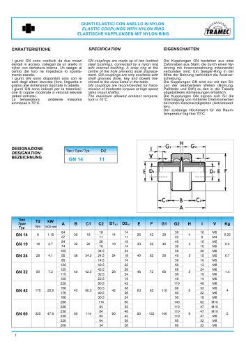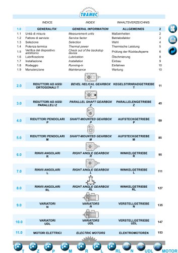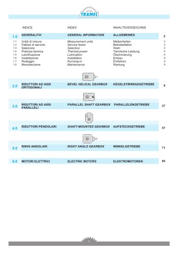
Catalog excerpts

TRAMEC RIDUTTORI A VITE SFK-SRK WORM SCHNECKENGETRIEBESENZA FINE SFK-SRK GEARBOXES SFK-SRK 2.1 Caratteristiche 2.3 Lubrificazione e posizioni di montaggio 2.4 Posizione morsettiera cavo passante 2.11 Lista parti di ricambio Characteristics Designation Lubrication and mounting position Terminal board position Technical data Moment of inertia Possible set-ups Dimensions Accessories Torque limiter with through hollow shaft Spare parts list
Open the catalog to page 1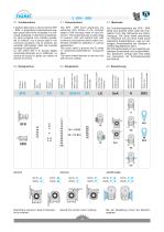
Albero uscita Output shaft Abtriebswelle Braccio di reazione Torque arm Drehmomentstütze Seconda entrata Additional input Zusatzantrieb 2.2 Designation Limitatore di coppia. Torque limiter Drehmomentbegrenzer Posizione di mont. Mounting position Einbaulage Die Schneckengetriebe der SFK - SRK Serie sind äußerst leicht dank der kompakten Form des Gehauses aus Aluminiumguss. Die Serie bietet verschiedene Versionen mit und ohne Füße sowie zahlreiche Zubehörteile an, was zur vielseitigen Anwendbarkeit der Getriebe in vielerlei Applikationen dient. Die Schneckenwelle ist aus legierten gehärteten...
Open the catalog to page 2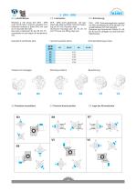
Riduttori a vite senza fine SFK - SRK sono forniti tutti e sempre completi di lu-brificante sintetico a base PAG con clas-se di viscosita ISO 320. Nei corpi in alluminio 30, 40, 50, 63, 75 e presente un solo tappo di riempimento olio. 2.3 Lubrication SFK - SRK worm gearboxes are supplied with PAG synthetic lubricant featuring an ISO 320 viscosity class. Aluminium housings size 30, 40, 50, 63 and 75 have one filling plug only. 2.3 Schmierung SFK - SRK Schneckengetriebe werden mit PAG synthetischen Schmierstoff Vis-kositatsklasse ISO 320 geliefert. Gehause aus Alumiunium GroUe 30, 40, 50, 63...
Open the catalog to page 3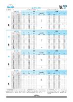
Technische Daten * ATTENZIONE: la coppia massima utiliz-zabile [T2M] deve essere calcolata utiliz-zando il fattore di servizio: T2M = T2 x FS' * WARNING: Maximum allowable torque [T2M] must be calculated using the following service factor: T2M = T2 x FS’ * ACHTUNG: das max. anwendbare Drehmoment [T2M] muss mit folgendem Betriebsfaktor berechnet werden: T2M = T2 x FS'
Open the catalog to page 4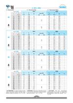
line 2 SFK-SRK TRAMEC 2.5 Dati tecnici 2.5 Technical data * ATTENZIONE: la coppia massima utiliz-zabile [T2M] deve essere calcolata utiliz-zando il fattore di servizio: T2M = T2 x FS' * WARNING: Maximum allowable torque [T2M] must be calculated using the following service factor: T2M = T2 x FS’ * ACHTUNG: das max. anwendbare Drehmoment [T2M] muss mit folgendem Betriebsfaktor berechnet werden: T2M = T2 x FS'
Open the catalog to page 5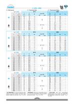
Technische Daten * ATTENZIONE: la coppia massima utiliz-zabile [T2M] deve essere calcolata utiliz-zando il fattore di servizio: T2M = T2 x FS' * WARNING: Maximum allowable torque [T2M] must be calculated using the following service factor: T2M = T2 x FS’ * ACHTUNG: das max. anwendbare Drehmoment [T2M] muss mit folgendem Betriebsfaktor berechnet werden: T2M = T2 x FS'
Open the catalog to page 6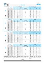
line 2 SFK-SRK TRAMEC 2.5 Dati tecnici 2.5 Technical data * ATTENZIONE: la coppia massima utiliz-zabile [T2M] deve essere calcolata utiliz-zando il fattore di servizio: T2M = T2 x FS' * WARNING: Maximum allowable torque [T2M] must be calculated using the following service factor: T2M = T2 x FS’ * ACHTUNG: das max. anwendbare Drehmoment [T2M] muss mit folgendem Betriebsfaktor berechnet werden: T2M = T2 x FS'
Open the catalog to page 7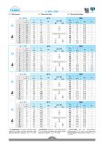
Technische Daten * ATTENZIONE: la coppia massima utiliz-zabile [T2M] deve essere calcolata utiliz-zando il fattore di servizio: T2M = T2 x FS' * WARNING: Maximum allowable torque [T2M] must be calculated using the following service factor: T2M = T2 x FS’ * ACHTUNG: das max. anwendbare Drehmoment [T2M] muss mit folgendem Betriebsfaktor berechnet werden: T2M = T2 x FS'
Open the catalog to page 8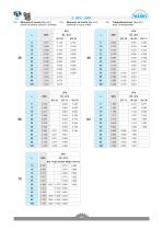
2 SFK-SRK Moments of inertia [Kg-cm2] (referred to input shaft) line 2.6 Momenti d' inerzia [Kg-cm2] (riferiti all'albero veloce in entrata)
Open the catalog to page 9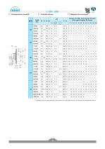
2 SFK-SRK 2.7 Predisposizioni possibili 2.7 Possible set-ups 2.7 Mogliche Vorrichtungen line * A richiesta, solo con corpo speciale / Upon request, only with special body / Auf Wunsch nur mit speziellen Korper
Open the catalog to page 10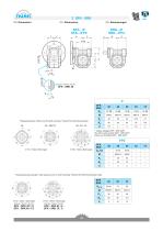
2.8 Dimensioni 2 SFK-SRK 2.8 Dimensions 2.8 Abmessungen SFK.../P SFK.../FP2 K E SRK.../P SRK.../FP2 L N _ E _ Flangia pendolare / Side cover for shaft mounting / Flansch fur Drehmomentstutze 30 40 - 50(FP2) 50 - 63 - 75 4 Fori / Holes / Bohrungen 8 Fori / Holes / Bohrungen Flangia pendolare speciale / Side special cover for shaft mounting /Flansch fur Drehmomentstutze notig. 4 Fori / Holes / Bohrungen Solo per / Only for / Nur fur SFK - SRK 40 / F1 SFK - SRK 40 / F2 8 Fori / Holes / Bohrungen Solo per / Only for / Nur fur SFK - SRK 63 / F.. SFK - SRK 75 / F..
Open the catalog to page 12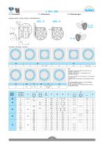
line 2 SFK-SRK TRAMEC 2.8 Dimensioni 2.8 Dimensions 2.8 Abmessungen Flangia uscita / Output flange /Abtriebsflansch N.B. La flangia uscita pud essere montata solo sul riduttore in versione P. Le flangie indicate con (*) necessitano di un coperchio speciale. The output flange is to be mounted to the gearbox P version only. A special cover is required for the flanges marked by (*). Der Abtriebsflansch darf nur auf das Getriebe Version P montiert werden Fur die Flansche mit (*) ausgezeichnet ist einen Sonderdeckel notig.
Open the catalog to page 13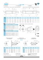
Albero lento semplice / Single output shaft/Standard Abtriebswelle Albero lento doppio / Double output shaft / Doppelte Abtriebswelle BR1 I loccola / Without bush / Ohne Buchse Braccio di reazione / Torque arm / Drehmomentstutze BR1 |BR2 Entrata supplementare (vite bisporgente) Additional input (double extended input shaft) Zusatzantrieb (beidseitige Welle) SFK Available options: Opzioni disponibili: Cuscinetti a rulli conici corona Tapered roller bearing for worm wheel Auf Anfrage ist folgendes Zubehor erhaltlich: Kegelrollenlager fur Schneckenrad
Open the catalog to page 14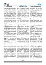
2.10 Limitatore di coppia cavo passante 2.10 Torque limiter with through hollow shaft 2.10 Drehmomentenbegrenzer mit durchgehender Hohlwelle Il limitatore di coppia viene consigliato in tutte quelle applicazioni che richiedono una limitazione sulla coppia trasmissibile per proteggere l’impianto e/o preservare il riduttore evitando sovraccarichi o urti indesiderati quanto inaspettati. È un dispositivo con albero dotato di cavo passante, con funzionamento a frizione, ed è integrato al riduttore, presentando un ingombro limitato. Concepito per lavorare a bagno d’olio, il dispositivo risulta...
Open the catalog to page 15All TRAMEC catalogs and technical brochures
-
COUPLINGS GN
1 Pages
-
Worm Gearboxes
46 Pages
-
ATEX cat.3 catalogue
35 Pages
-
ATEX cat.2 catalogue
36 Pages
-
Motors/Drive Stepless
6 Pages
-
Motors/Drive Brushless
12 Pages
-
Inverter IS7
5 Pages
-
Inverter IC5
3 Pages
-
Inverter IP5A
4 Pages
-
Inverter IG5A
5 Pages
-
Inverter IE5
3 Pages
-
BCFK - BCRK Series
20 Pages
-
SCFK - SCRK Series
20 Pages
-
BFK - BRK Serie
18 Pages
-
SFK - SRK Series
18 Pages
-
TLS Line Catalogue
96 Pages
-
Worm gearboxes catalogue
144 Pages
-
Motion & Control
69 Pages
-
CI3050
2 Pages
-
VM Series complete catalogue
24 Pages
-
H Series complete catalogue
36 Pages
-
K Series complete catalogue
36 Pages
-
X Series complete catalogue
40 Pages
-
EP series complete catalogue
30 Pages
-
REP series complete catalogue
32 Pages
-
UDL Series Complete Catalogue
16 Pages
-
N Series Complete Catalogue
22 Pages
-
L Series Complete Catalogue
26 Pages
-
R Series Complete Catalogue
26 Pages
-
M Series Complete Catalogue
20 Pages
-
P Series Complete Catalogue
26 Pages
-
Z Series Complete Catalogue
34 Pages
-
T Series Complete Catalogue
44 Pages
-
BRUSHLESS DRIVE
12 Pages
-
Motoinverter
6 Pages
-
Planetary gearboxes catalogue
52 Pages
-
GN series catalogue
1 Pages
-
RL series catalogue
18 Pages
-
TLS series catalogue
96 Pages
Archived catalogs
-
General catalogue (EN, DE, IT)
88 Pages


