

dynafor™

dynafor™
- Indicator LED for manufacturer use.
- LCD graphic screen with 128 x 64 pixels, dimensions 67 x 40 mm.
- Keys for various functions including 'esc', backlighting, on/off, and browsing options.
- Safety wrist strap and charger socket included.
- Models range from LLX2 0.5 t to LLX2 10 t with varying maximum capacities and test loads.
- Precision of 0.1% according to ISO 376 at 21°C.
- Autonomy ranges from 300 to 3000 hours depending on functions.
- Radio scope of 80 meters in open field, using 2.4 GHz RF technology.
- Operating temperature from -20° to 40°C.
- Chain anchoring accessories with treated steel pins and DIN 6799 support collars.
- Cable anchoring accessory compatible with relevant regulations.
- Ensure no stress value is shown when not in use and check battery levels.
- Installation requires robust anchoring points and compatible accessories.
- Utilization should avoid compression, twisting, or flexing.
- Uninstallation requires ensuring no traction stress is present.
- Prohibited to use for lifting people without risk analysis.
- Do not modify the appliance housing or exceed maximum capacity.
- Displays an overload message and emits a beep if capacity exceeds 15%.
- Consists of one sensor and one display unit for measuring stress.
- Radio link set at the factory but can be configured by the user.
- Standard display screen shows sensor stress and battery levels.
- Icons for menu access, unit selection, tare function, and peak stress save.
- Main menu includes functions for saving measurements and configuring network settings.
- Adding Sensors: Sensors can be added to the Master display unit either on the same channel or a different one. For same channel, sensors are automatically associated. For different channels, the display unit scans and identifies sensors within an 80m radius.
- Adding Slave Display Units: Similar to sensors, Slave units can be added on the same or different channels. The process involves scanning and selecting units within an 80m radius.
- The display menu remains consistent regardless of the number of sensors. It shows measurements, battery levels, and allows navigation through functions using arrows.
- The optional PC connection kit includes a USB lead and software for managing up to 8 sensors, allowing data processing and printing.
- Battery Management: Regular checks and replacements are necessary for sensor batteries and display unit power packs.
- Regulatory Checks: Devices come with adjustment certificates and can be calibrated to ISO 376 standards.
- Troubleshooting: Common issues include battery failures, electronic faults, and communication errors, with solutions involving resets and contacting after-sales service.
- Devices should be stored and transported in original packaging, with batteries removed. Disposal must comply with local regulations.
- All product labels must remain readable, and replacements are available from the manufacturer if needed.
Catalog excerpts

0,5 / 1 / 2 / 3,2 t 5 / 6,3 t 10 t ® ® Instructions d’emploi et d’entretien Operation and maintenance manual Gebruiks-en onderhoudsvoorschrift Gebrauchs- und Wartungsanleitung Français English Nederlands Deutsch FR GB NL D dynafor™ 1 Dynamomètres électroniques série LLX2 Series LLX2 Electronics Dynamometers Elektronisches dynamometers serie LLX2 LLX2 Elektronische Zugkraft-Messgeräte
Open the catalog to page 1
2 F SOMMAIRE page CONSIGNES PRIORITAIRES • • • • • • • • • • • • • • • • • • • • • • • • • • • • • • • • • • • • • • • • 4 1. PRÉSENTATION • • • • • • • • • • • • • • • • • • • • • • • • • • • • • • • • • • • • • • • • • • • • • • • 5 1.1. Principe de fonctionnement • • • • • • • • • • • • • • • • • • • • • • • • • • • • • • • • 5 1.2. Description et marquage • • • • • • • • • • • • • • • • • • • • • • • • • • • • • • • • • • 6 1.2.1. Capteur • • • • • • • • • • • • • • • • • • • • • • • • • • • • • • • • • • • • • • 6 1.2.2. Boîtier d'affichage • • • • • • • • • • • • • • • • • • • • • • • •...
Open the catalog to page 2
3 F 6.3. Fonctions avancées • • • • • • • • • • • • • • • • • • • • • • • • • • • • • • • • • • • • • 18 6.3.1. Menu principal • • • • • • • • • • • • • • • • • • • • • • • • • • • • • • • • • 18 6.3.1.1. Menu Fonctions • • • • • • • • • • • • • • • • • • • • • • • • • 18 6.3.1.1.1. Enregistrement • • • • • • • • • • • 19 6.3.1.1.2. Cumul • • • • • • • • • • • • • • • • • 20 6.3.1.1.3. Seuils • • • • • • • • • • • • • • • • • • 21 6.3.1.2. Menu paramétrage • • • • • • • • • • • • • • • • • • • • • • • 22 6.3.1.2.1. Date et heure • • • • • • • • • • • • 22 6.3.1.2.2. Coefficients • • • • • • •...
Open the catalog to page 3
4 F CONSIGNES PRIORITAIRES ATTENTION. Situation éventuelle. Dangereuse. Risques de blessures légères ou de dégats matériel. Appareil entièrement protégé par une isolation double ou renforcée. 1. Avant d’installer et d’utiliser cet appareil, il est indispensable, pour sa sécurité d’emploi et son efficacité, de prendre connaissance de la présente notice et de se conformer à ses prescriptions. Un exemplaire de cette notice doit être conservé à disposition de tout opérateur. Des exemplaires supplémentaires peuvent être fournis sur demande. 2. Ne pas utiliser cet appareil si l’une des étiquettes fixées...
Open the catalog to page 4
5 F 1 PRÉSENTATION Les dynamomètres dynafor™ LLX2 sont des appareils de précision (0,1%, ISO 376 . 21°C) (I.P. 67 = 0,2%), pour la mesure des forces de traction et d'indication de charges. La gamme de capacité s'étend de 500 daN à 10000 daN. Un ensemble dynafor™ LLX2 est constitué d'un capteur et d'un boîtier d'affichage amovible. Une liaison radio bidirectionnelle utilisant la bande de fréquence 2,4 GHz relie les deux éléments. 16 canaux radio sont utilisés. Chaque boîtier d'affichage et chaque capteur possède sa propre adresse qui permet son identification sans équivoque en cas de configuration...
Open the catalog to page 5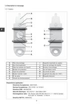
6 F 1.2 Description et marquage 1.2.1 Capteur A B C D E F G H I J K O N M L Dispositions appliquées : Directives Européennes : 98/37/CEE - Normes Européennes : EN 12100-1 et 12100-2 Directice CEM : 89/336/CEE Sécurité Electrique : IEC 61010-1 2de Edition 2001 Homologations radio : CE :Essais radio EN 300 440-2 V1.1.1 / USA & Canada : FCC part 15 / Australie : C-Tick ID Directive R&TTE (1999/5/CE) A Tête d’accrochage I Capacité maximale du capteur B Axe d’accouplement J Joue de centrage de manille C Clips de maintien de l’axe B K Anneau d’accrochage D Bumper de protection L Vis de fixation de...
Open the catalog to page 6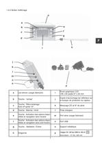
7 F 1.2.2 Boîtier d'affichage a b c d e f g h i o j k l m n o p a Led témoin (usage fabricant) i Écran graphique LCD 128 x 64 pixels 67 x 40 mm b Touche : “echap” j Ergots d’accrochage de l’afficheur sur le bumper de protection du capteur c Touche : Rétro-éclairage. Auto off après 10” k Marquage CE et N° de série d Touche : Marche / Arrêt l Prise chargeur e Touche : Activation des options disponibles et navigation sens horaire m Port série (usage fabricant) f Touche : Activation des options disponibles et navigation sens anti-horaire n Port USB g Touche : Validation / Entrer o Support métallique...
Open the catalog to page 7All TRACTEL catalogs and technical brochures
 travrail
2 Pages
 Fall arrest equipment
1 Page
 Easy Jacket
1 Page
 AMERICAN JACKET
1 Page
 HT Ladytrac Harness
2 Pages
 Platforms and Cradles
16 Pages
 HT Transport
2 Pages
 HT Promast
2 Pages
 HT Greentool
2 Pages
 HT Electra
2 Pages
 HT Easyclimb
2 Pages
 HT 56
HT 562 Pages
 HT 55
HT 552 Pages
 Wind Turbine
23 Pages
 HT 54
HT 542 Pages
 LLX2
LLX22 Pages
 dynafor TM range LLXh
2 Pages
 ET10
ET102 Pages
 HT22
HT221 Page
 FALL ARREST EQUIPMENT
2 Pages
 Travflex - EN 795 Class C
24 Pages
 dynafor® MWX, MWX-TR
8 Pages
 dynafor™ LLX, LLX-TR
8 Pages
 Longe - EN 354
40 Pages

