
- Catalogs
- TPS Elektronik GmbH
- TPS-BM 142250/142400/142650


- Company
- Products
- Catalogs
- News & Trends
- Exhibitions
TPS-BM 142250/142400/142650
TPS-BM 142250/142400/142650
Document Overview
This technical document appears to be a product or component datasheet or installation guide related to electronic equipment, possibly a fan unit with signal lamps and mounting provisions. The document includes installation hole specifications, component placement, and some technical parameters.
Main Sections and Summaries
1. Installation and Mounting Specifications
- Two sets of holes labeled 'A' and 'B' are reserved for installation purposes.
- Mounting holes are designed to accommodate the installation of the fan guard and signal lamp.
- The document references a "prominent plane" with a thickness of 2mm, likely indicating a mounting surface or clearance requirement.
- Back view illustrations show the placement of the signal lamp and fan guard relative to the mounting holes.
2. Component Descriptions
- Signal lamp: Positioned prominently, likely for status indication.
- Fan guard: Protective component installed over the fan, ensuring safety and airflow management.
3. Technical Parameters and Notes
- The document contains multiple references to technical parameters, possibly including electrical or mechanical specifications, but these are obscured or encoded in the provided text.
- There are indications of compliance or reference to standards, but specific norms or certifications are not clearly extractable.
4. Visual Aids and Diagrams
- Several diagrams or schematic views are referenced, showing hole placements, component locations, and installation views.
- Key data extracted includes the positioning of installation holes and the relative placement of the fan guard and signal lamp.
Critical Information and Recommendations
- Ensure correct use of installation holes 'A' and 'B' for secure mounting.
- Maintain the 2mm clearance or prominent plane as specified for proper installation.
- Verify the orientation of the signal lamp and fan guard as per the back view diagrams to ensure correct assembly.
- Follow any additional technical specifications or standards referenced in the full document for compliance and safety.
Limitations
The document text is partially corrupted or encoded, limiting the extraction of detailed technical specifications, electrical parameters, or normative references. The summary is based on the legible and interpretable portions of the document.
Catalog excerpts

Bidirecitonal Power Module Specification TPS-BM142250/TPS-BM142400/TPS-BM142650
Open the catalog to page 1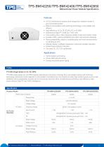
TPS-BM142250/TPS-BM142400/TPS-BM142650Bidirecitonal Power Module SpecificationFeatures • AC-DC bidirectional isolation and energy flow, reliable inverter in grid-connected system • Mature and excellent soft switching technology, more reliable and efficient • Bidirectional high PF >0.99, lowTHDi <5% • Fast swithing time <10ms between rectifer mode and inverter mode • Excellent EMC, meeting EN55032 and other international standards • Strong adaptability, adapt to unstable grids and harsh environments, no derating at 45°C • Modular design, intelligent expansion, automatic parallel operation • Perfect...
Open the catalog to page 2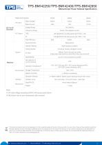
TPS-BM142250/TPS-BM142400/TPS-BM142650Bidirectional Power Module Specification DC To AC Direction This electronic device must not be disposed of in the household waste at the end of its service life, For your return, there are free collection points for electrical appliances and, if necessary, additional points of acceptance for the reuse of the devices in your area,The addresses an be obtained from your city or cummunal administration, If the old electrical or electronic device contains personal data, you are esponsible for deleting it before you return it, Further information: www,elektrogesetz,de...
Open the catalog to page 3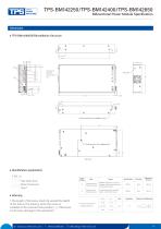
TPS-BM142250/TPS-BM142400/TPS-BM142650Bidirectional Power Module SpecificationDimension• TPS-BM142650SI(R)lnstallation Structure • Identification explanation7-M3^6 ■■ I L Hole depth 6mm-Metric thread sizeTotal 7• Warning I.The length of the screw shall not exceed the depth of the hole in the drawiny when the screw is installed at the reserved hole position (t). Otherwise it will cause damage to the equipment. Dimensional tolerance
Open the catalog to page 4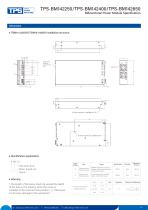
TPS-BM142250/TPS-BM142400/TPS-BM142650Bidirectional Power Module SpecificationDimension• TBM14-2250SIR/TBM14-2400SI Installation structure A L Hole depth 6mm-Metric thread sizeTotal 6• Warning I.The length of the screw shall not exceed the depth of the hole in the drawiny when the screw is installed at the reserved hole position (t). Otherwise it will cause damage to the equipment. Dimensional tolerance
Open the catalog to page 5All TPS Elektronik GmbH catalogs and technical brochures
 TO Series
9 Pages
 TPS-BM143400SI(R)
4 Pages
 EA-PSI 10000 4U
97 Pages
 EA-PS 100004U
75 Pages
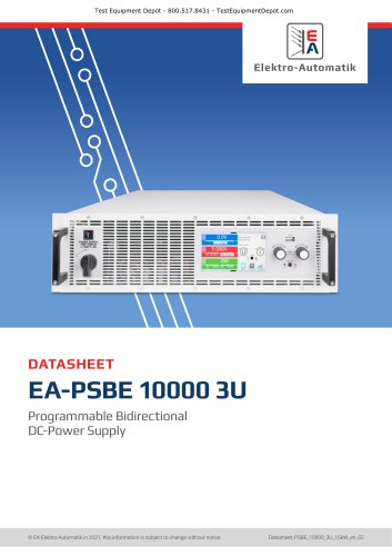 EA-PSBE 10000 3U
15 Pages
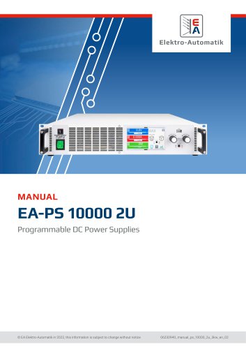 EA-PS 10000 2U
68 Pages
 TPS-MPT36S
2 Pages
 FSP090-ABAN3_spec
8 Pages
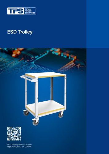 ESD Trolley
2 Pages
 ESD Workstation
4 Pages
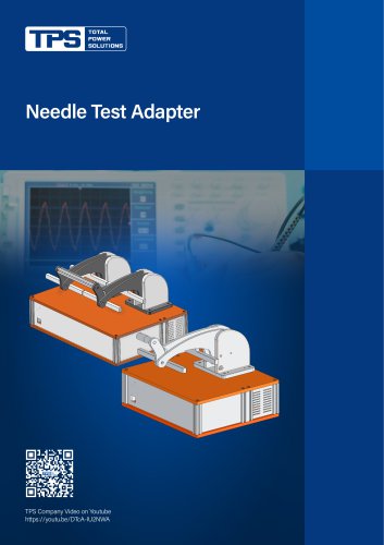 Needle Test Adapter
2 Pages
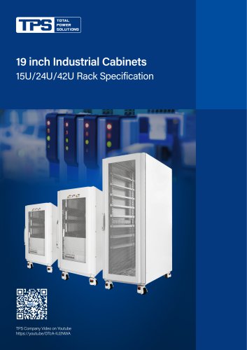 19 inch Industrial Cabinets
5 Pages
 Aluminum Profile Heat Sink
8 Pages
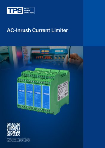 AC-Inrush Current Limiter
3 Pages
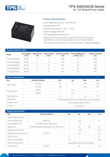 TPS-AWD1023S Series
4 Pages
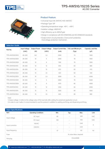 TPS-AWS10/1523S Series
5 Pages
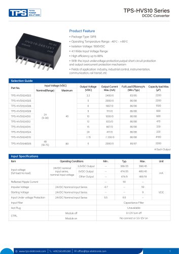 TPS-HVS10 Series
4 Pages
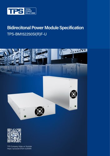 TPS-BM152250SI(R)F-U
4 Pages
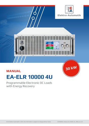 EA-ELR 10000 4U
96 Pages
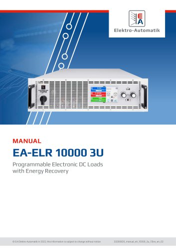 EA-ELR 10000 3U
95 Pages
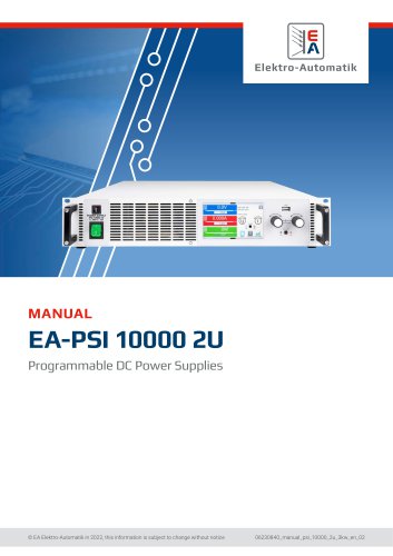 EA-PSI 10000 2U
92 Pages
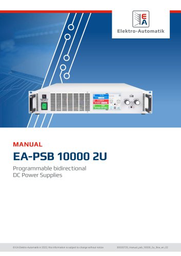 EA-PSB 10000 2U
105 Pages
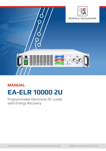 EA-ELR 10000 2U
91 Pages
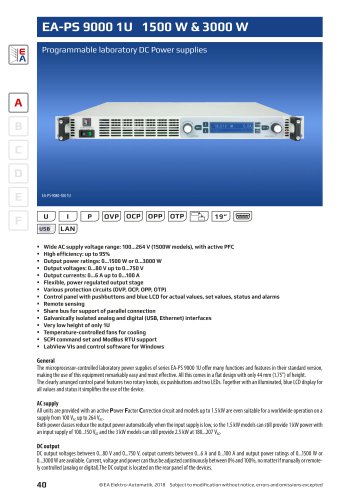 EA-PS 9000 1U
4 Pages
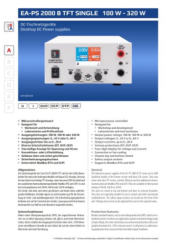 EA-PS 2000 B
4 Pages
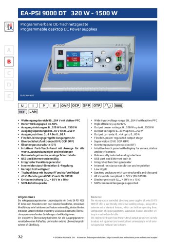 EA-PSI 9000 DT
6 Pages
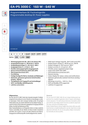 EA-PS 3000C
4 Pages
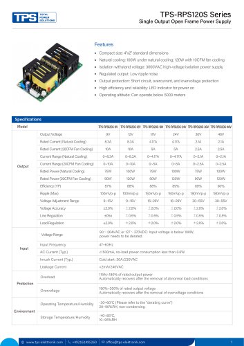 TPS-RPS120S Series
2 Pages
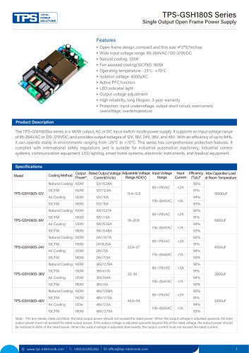 TPS-GSH180S Series
4 Pages
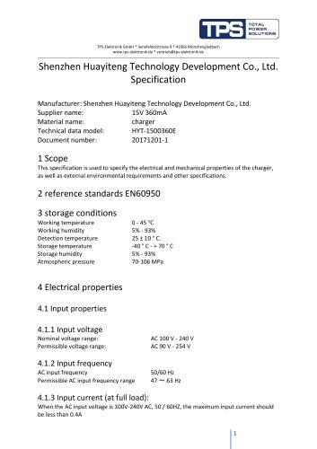 HYT-1500360E
6 Pages
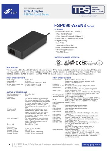 FSP090-AxxN3 Series
4 Pages
 FSP550-50FS
49 Pages
 FSP220-50FGBBI
10 Pages
 FSP300-70PFL(SK)
14 Pages
 FSP300-50UCB
14 Pages
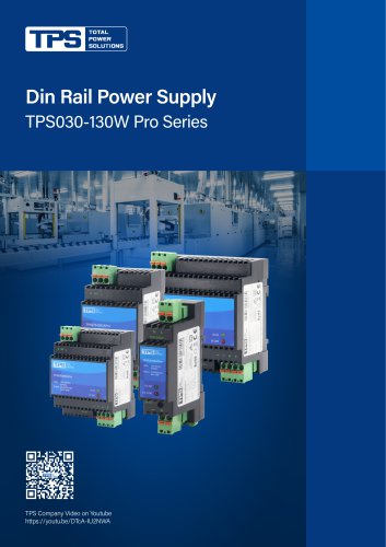 TPS030-130W Pro Series
4 Pages
 TPS100-320W Peak DR+ Series
4 Pages
 TPS010-100 GP Series
4 Pages





- Power supply unit
- DC power supply
- AC/DC power supply
- Transformer
- Dry transformer
- Metal cart
- CE power supply
- Propeller fan
- Transport trolley
- Air circulation fan
- Floor-mounted cabinet
- Industrial fan
- Single-output power supply
- Air blower
- Power supply for industrial applications
- Door cabinet
- AC fan
- Switched-mode power supply
- Workbench
- Centrifugal blower