
- Catalogs
- TPS Elektronik GmbH
- EA-ELR 10000 2U


- Company
- Products
- Catalogs
- News & Trends
- Exhibitions
EA-ELR 10000 2U
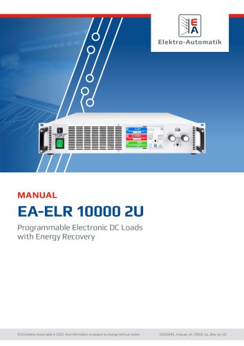
EA-ELR 10000 2U
- Document Usage: The manual should be kept near the equipment for reference and transferred with the equipment if relocated.
- Copyright: Unauthorized modification or use of this document is prohibited.
- Validity: Applicable to specific EA-ELR models listed in the document.
- Symbols and Warnings: Various symbols indicate potential hazards, such as electric shock risks.
- Warranty: Covers functional competence and performance parameters from delivery.
- Limitation of Liability: Manufacturer is not liable for misuse, unauthorized modifications, or use of unauthorized parts.
- Equipment must be returned to the manufacturer for disposal according to European regulations.
- Explanation of product labeling, including series, voltage, and current specifications.
- Designed as a variable voltage/current source or sink, to be used in suitable equipment like a 19” rack.
- Safety Notices: High voltage parts must be covered during operation. Follow specific safety rules when working with electrical devices.
- Operator Responsibility: Operators must ensure safety compliance and provide necessary training and equipment to users.
- User Requirements: Only qualified individuals should operate the equipment.
- Operating Conditions: The device operates between 0°C to 50°C and must be acclimatized if condensation occurs. It should be used in dry rooms with good air circulation.
- Cooling: The device uses air cooling with a fan to regulate temperature, and dust must not obstruct airflow.
- General Specifications: Includes display, controls, AC input, DC input static and dynamic specifications, protective functions, and insulation details.
- Interfaces: The device includes digital and analog interfaces for communication and monitoring.
- Safety and EMC: Compliance with various safety and EMC standards, including EN 61010-1 and EN 55011.
- Environmental Conditions: Operating temperature, humidity, altitude, and pollution degree specifications.
- Mechanical Construction: Details on cooling, dimensions, and weight.
General Description: The ELR 10000 2U series are energy-recovering electronic loads that convert consumed DC energy back into the local mains with up to 95% efficiency. They feature an integrated function generator for creating set point curves and support battery and solar module testing. Remote control is facilitated through USB, Ethernet, and optional digital interfaces like RS232 and CANopen. The devices can be connected in parallel for increased power capacity, supporting up to 64 units for a total of 192 kW.
Block Diagram: The block diagram highlights digital, microprocessor-controlled components that can be updated via firmware. Key components include the controller, communication module, and HMI.
Scope of Delivery: Includes the electronic load device, remote sensing plugs, USB cable, terminal covers, USB stick with documentation, and a cable tie.
Accessories: Available accessories include interface modules for various digital interfaces and software licenses for enhanced control features.
Options: Options include 19” power racks for creating test systems, available in various configurations.
The Control Panel (HMI): Features a touchscreen display, rotary knobs, and a USB port. The display shows actual and set values for voltage, current, power, and resistance. The rotary knobs allow for manual adjustment of these values.
Touchscreen Display: Displays actual and set values, status information, and allows for menu access. The display is touch-sensitive and can be operated by finger or stylus.
Rotary Knobs: Used for adjusting set values in manual operation. They have a pushbutton function for cursor movement.
Pushbutton Function: Allows for cursor movement during value adjustment.
Resolution of Displayed Values: Set values can be adjusted in fixed increments, with the number of decimal places depending on the device model.
USB Port (Front Side): Used for loading/saving sequences and recording data. Supports USB 2.0 and 3.0 sticks formatted in FAT32.
USB Port (Rear Side): Used for device communication and firmware updates. Supports ModBus RTU protocol or SCPI language.
Interface Module Slot: Allows for installation of various interface modules for enhanced connectivity.
Analog Interface: Provides remote control via analog or digital signals, with adjustable voltage ranges.
“Share BUS” Connector: Details not fully provided in the excerpt.
The Share BUS is a bidirectional digital bus used for connecting a bus master unit to slave units in a master-slave configuration. It is compatible with all 10000 series devices, but only supports connections between the same device types, such as power supplies with power supplies or electronic loads with electronic loads. For ELR 10000 devices, only identical or different ELR 10000 models can be used as slave units.
The Sense connector compensates for voltage drops along DC cables by connecting to an external source. In a master-slave system, remote sensing is wired only to the master, which forwards compensation to the slaves via the Share BUS. The Sense cover must be installed during operation due to hazardous voltage risks.
The device includes RJ45 sockets for connecting multiple compatible devices via a digital RS485 bus to create a master-slave system. Connections should be short, and the bus should be terminated if required, which is activated in the device setup menu.
The RJ45 LAN/Ethernet port allows remote control or monitoring via a website or TCP/IP access. The device can be controlled using SCPI or ModBus RTU protocols, with ModBus TCP supported by an optional interface module. Network setup can be manual or via DHCP, with automatic transmission speed and duplex mode.
Transport and Storage: Devices should not be transported while switched on or connected. Original packaging is recommended for transport and storage to prevent damage and corrosion.
Unpacking and Visual Check: Inspect the equipment for damage and completeness before commissioning. Damaged devices should not be operated.
Installation: Devices should be installed in a 19” rack or cabinet with proper ventilation and touch protection. AC connections must be made by qualified personnel, and devices should be fused externally according to current ratings.
Energy Recovery: Devices feed energy back into the local or public grid. Operators must comply with local regulations and may need to install a network & system protection device.
Connection to AC Supply: AC supply connections require suitable cable cross sections and must be fused externally. Devices support 220/230/240 V or 110/120 V, with automatic power derating for lower voltages.
Connection to DC Sources: DC connections require consideration of cable weight and strain, with no false polarity protection inside the device. Proper cross section and electric strength of DC cables are essential.
The document outlines the recommended cable sizes for different current ratings, emphasizing the need for increased cross-section for longer cables to prevent voltage loss and overheating. It specifies the use of flexible cables with ring lugs for DC terminal connections, and provides details on the installation of plastic covers for contact protection.
DC Terminal and Cable Management:
The DC terminal requires the use of ring lugs with a 6.5 mm hole. Two plastic covers are provided for contact protection, with installation options to accommodate different cable directions and bending radii.
Remote Sensing Connection:
Remote sensing is effective only during constant voltage operation. Recommendations include using cables with at least 0.5 mm² cross-section for lengths up to 5 meters, and ensuring proper connection to avoid damage. The dielectric strength of sense wires must match the DC voltage rating.
Grounding and Safety:
Grounding of the DC terminal is crucial, with specific potential shift limits for the negative DC terminal pole. Proper external protection must be reinstated if any DC pole is grounded.
Interface Module Installation:
Interface modules are user-retrofittable and exchangeable. ESD protection procedures must be followed, and the device should be switched off during module insertion or removal.
Analog Interface and Share Bus Connection:
The analog interface uses a 15 pole D-sub connector, and the Share Bus connectors are used for parallel operation voltage balancing. Proper procedures for connection and disconnection are advised.
USB Port and Driver Installation:
The USB port allows remote control via a PC. Windows drivers are included, while Linux and MacOS users must search for suitable drivers online.
Initial Commissioning and Firmware Updates:
Initial commissioning involves checking cable cross-sections and factory settings. Similar checks are required after firmware updates or long periods of non-use.
Operation and Safety Notes:
Only trained personnel should operate the device. Safety covers must be used for models generating dangerous voltages. The device should not be run below 10% voltage and current to ensure technical values are met.
Operating Modes:
The document describes various operating modes including constant voltage (CV), constant current (CC), constant power (CP), and constant resistance (CR). Each mode has specific characteristics and operational guidelines.
Voltage Regulation:
In CV mode, the device maintains a constant voltage unless current or power limits are reached. Transient times and voltage regulation speed settings are discussed.
Current and Power Regulation:
CC mode maintains constant current, switching to power limiting if necessary. CP mode keeps DC power constant, with auto-range principles applied.
Power Derating:
Devices operate on common grid voltages and switch to derating mode at low input voltages, reducing available DC power. Full power is available only with AC voltages from 208 V or higher.
Resistance Regulation:
CR mode is based on a variable internal resistance, with the load setting internal resistance to a user-defined value according to Ohm’s law.
The document outlines the specifications of an electronic load device, emphasizing its ability to handle high input currents at low voltages. It operates in constant resistance mode, indicated by 'CR' on the display, and can be monitored via a digital interface.
Dynamic Characteristics and Stability
The device features short rise and fall times due to a high bandwidth regulation circuit. Instabilities may occur when testing sources with their own regulation circuits, such as power supplies, due to insufficient phase and gain margins. Solutions include adjusting the internal voltage regulator speed (Slow, Fast, Normal) and adding capacitance to the DC input.
Alarm Conditions
The document details various alarm conditions, including Power Fail, Overtemperature, Overvoltage, Overcurrent, Overpower, and Share Bus Fail. Each alarm condition is signaled optically and acoustically, with specific actions to be taken depending on the alarm type.
Manual Operation
Instructions for switching the device on and off are provided, including the use of a toggle switch and external cutouts. The device can be configured via a menu accessed by touch, with settings for DC input state, remote control, and alarm signaling.
Configuration via Menu
The settings menu allows for the configuration of operating parameters, including presets for voltage, current, power, and resistance. Protection thresholds for overvoltage, overcurrent, and overpower can be adjusted. The menu also includes options for remote control, voltage controller speed, and analog interface settings.
Additional Features
The document mentions features like SEMI F47 compliance, master-slave mode configuration, and display backlight settings. It also provides guidance on initializing the master-slave system.
The document outlines the configuration of USB logging, including the format of CSV files generated. The default separator is a semicolon, but it can be changed to a comma for US standards. Logging can include units like V, A, and W, which can be deactivated. Logging intervals can be set between 500 ms to 5 s. Logging can be manually controlled or set to start/stop with DC input changes.
Device Reset and Profiles
The device can be reset to factory defaults, and user profiles can be loaded and saved. An overview menu displays set values, alarm thresholds, and event settings.
Communication Settings
The document details settings for digital communication via USB, Ethernet, and optional interface modules. Ethernet settings include DHCP, IP address, subnet mask, and gateway configurations. CANopen and Profibus settings include baud rate and node address configurations. ModBus and SCPI protocols can be enabled or disabled.
HMI Setup
The HMI setup includes language selection, sound settings, clock setup, and backlight settings. The backlight can be set to turn off after 60 seconds of inactivity.
Adjustment Limits
Adjustment limits can be set for voltage, current, power, and resistance to protect applications from overvoltage. Limits are adjustable from 0 to 102%, except for specific models.
Operating Modes
The device supports three operating modes: U/I, U/P, and U/R. These modes can be changed using rotary knobs or on-screen controls. The operating mode depends on the set values when the DC input is active.
Manual Adjustment
Manual adjustment of set values for voltage, current, and power is possible using the device's rotary knobs.
The document outlines the configuration of resistance values in "R mode," which must be activated separately. Values can be adjusted using rotary knobs for continuous changes or a numeric pad for larger steps. Changes are submitted immediately, regardless of the DC input state. Limits may apply, and notifications appear when limits are reached.
Adjusting Set Values:
Set values for voltage (U), current (I), power (P), or resistance (R) can be adjusted via rotary knobs or direct input. The rotary knobs allow for continuous adjustment, while the numeric pad allows for direct input. Limits are indicated on the display when reached.
Switching DC Input:
The DC input can be switched on or off manually or remotely. Manual operation requires the On/Off button, and remote operation can be controlled via analog or digital interfaces.
USB Logging:
Data can be recorded to a USB stick in CSV format. Logging is mobile and does not require a PC. Configuration includes setting logging intervals and start/stop conditions. USB logging is not available if battery test logging is active.
Graph Feature:
The device includes a graph feature for visualizing voltage, current, and power values. It is not a recording feature but can be accessed anytime via the quick menu.
Remote Control:
Remote control is possible via built-in interfaces (analog, USB, Ethernet) or optional modules. Control can be switched between manual and remote, with specific settings to allow or inhibit remote control.
Interface Monitoring:
Interface monitoring ensures the device does not operate uncontrolled if communication fails. It is valid for one digital interface and based on a user-definable timeout.
Analog Interface:
The analog interface allows remote control of current, voltage, power, and resistance. It supports remote status and alarm monitoring and requires concurrent setting of voltage, current, and power values.
The device setup allows configuration of the voltage range, with reference voltages of 5V or 10V corresponding to 0-100% of rated values. Configuration details are found in section 3.4.3. Set values are limited by adjustment limits to prevent excess values for DC input.
Interface Usage Notes:
Upon powering the device, AI signals may show undefined statuses. Analog remote control requires activation via pin REMOTE, except for pin REM-SB. Set value inputs must not be left unconnected during remote control.
Acknowledging Device Alarms:
Device alarms during remote control will switch off the DC input. Alarms are indicated on the front display and can be configured in the device menu. Acknowledgment is done by toggling pin REM-SB.
Analog Interface Specification:
The document provides detailed specifications for each pin, including voltage and current set values, reference voltage, and alarm indicators. The interface is sampled by a digital micro-controller, affecting resolution.
Application Examples:
Examples include switching the DC input with pin REM-SB and remote control of current and power. The document advises using low resistance contacts for switching and highlights the importance of considering input voltage ranges.
Alarms and Monitoring:
Device alarms such as overvoltage and overheating are distinct from user-defined events. Alarms typically switch off the DC input and require acknowledgment. Configurable alarms include OVP, OCP, and OPP, while non-configurable alarms are based on hardware conditions like power fail and overtemperature.
Configuring Alarm Thresholds:
Thresholds for adjustable device alarms can be configured via the protection menu when the DC input is off.
The document outlines the configuration of protection thresholds and alarm settings for a device. Users can adjust the default protection threshold of 110% if unsuitable and choose to enable an acoustic signal for alarms or user-defined events. Configuration is accessible via a quick menu.
User Defined Events
User-defined events can be configured to monitor voltage, current, and power levels. These events, such as UnderVoltage Detection (UVD) and OverCurrent Detection (OCD), are only active when the DC input is on. They can trigger actions like alarms to protect sensitive applications.
Locking Mechanisms
The document describes how to lock the Human-Machine Interface (HMI) and adjustment limits to prevent unauthorized changes. Locking can be done using a PIN code, and unlocking requires entering the correct PIN.
User Profiles
Users can save and load settings using profiles. Up to five user profiles can be created, each storing specific settings and values. Profiles facilitate quick adjustments without manual reconfiguration.
Function Generator
The built-in function generator can create various signal forms, such as sine, triangle, and rectangular waves. It is configurable for both manual and remote control, with limitations on use when resistance mode is active. The generator's operation involves setting values for voltage, current, and power, with specific configurations for master-slave systems.
Manual Operation and Function Control
Functions can be selected and configured via the touchscreen when the DC input is off. Parameters such as amplitude and offset are adjustable, and functions can be started or stopped using the interface or physical buttons. Alarms or protection events automatically stop functions and switch off the DC input.
Sine Wave Function
The sine wave function allows configuration of frequency, amplitude, and offset. It generates a sine wave signal applied to the selected set value, such as current, with calculations for maximum power input based on amplitude and offset values.
- Input Power Calculation: With an input voltage of 100 V, a sine wave current with an amplitude of 30 A and an offset of 50 A results in a maximum input power of 8000 W.
- Triangular Function: Configurable parameters include amplitude, offset, and time intervals for rising and falling edges. The cycle time is the sum of these intervals, determining the frequency.
- Rectangular Function: Parameters include amplitude, offset, and time intervals for pulse and pause widths. The duty cycle is defined by these intervals, with the period being the sum of t1 and t2.
- Trapezoidal Function: Configurable parameters include amplitude, offset, and time intervals for positive slope, top value, negative slope, and base value. The function can be adjusted to form triangular or rectangular pulses.
- DIN 40839 Function: This function replicates automobile battery voltage during engine starting, based on DIN 40839 / EN ISO 7637 standards. It involves five sequence points with configurable start and end voltages, ramp times, and cycles.
- Arbitrary Function: Offers 99 sequence points for complex function curves, applicable to either current or voltage. Parameters include AC/DC start and end values, frequency, angle, and time. The function allows for the creation of complex waveforms by linking sequence points.
- Sequence points can be saved or loaded via USB in a CSV format. The file must contain 99 rows with specific parameters and be stored in a designated folder on the USB stick.
This section outlines the procedures for accessing the function selection menu and managing files for sequence setup. Users can import or export sequence tables via a USB stick. The process involves selecting the 'Arbitrary' group, navigating to 'Sequence setup', and using 'Import/Export' options to load or save files. Files must be compatible and correctly formatted to avoid errors.
Ramp Function
The ramp function allows configuration of start and end points, with parameters for time delays before ramp-up or ramp-down. The function generates a ramp between specified values and stops automatically after 10 hours unless manually stopped. For repeating ramps, the Trapezoid function is recommended.
IU Table Function
This function sets a DC input current based on voltage, using a table of 4096 values. The table can be uploaded via USB or remote control. Files must be in CSV format and adhere to specific naming and formatting rules. Incorrect files will be rejected.
Battery Test Function
The battery test function is designed for discharging batteries in industrial or laboratory settings. It operates in static or dynamic discharge modes, with configurable parameters for current, power, and resistance. Stop conditions include discharge end voltage, capacity limits, and time limits. Data can be logged to a USB stick.
MPP Tracking Function
The Maximum Power Point (MPP) tracking function simulates solar panel behavior. It offers four modes, with MPP1 finding the MPP and MPP2 tracking it continuously. Parameters include open circuit voltage, short-circuit current, and tracking interval. The function records data for analysis and evaluation.
1. Mode MPP2: This mode involves tracking the Maximum Power Point (MPP) of solar panels by measuring open circuit voltage (UOC) and short-circuit current (ISC). The tracking interval can range from 5 to 60000 ms, and the tolerance below the MPP is defined by Delta P.
2. Mode MPP3: Known as "fast track," this mode skips the initial MPP finding step and directly uses user-defined MPP values (UMPP, PMPP). It is useful for repetitive tests where MPP values are known.
3. Mode MPP4: This mode allows users to define a curve with up to 100 voltage points, which can be loaded from a USB stick. The function can be repeated up to 65535 times, and results are displayed as voltage (UMPP), current (IMPP), and power (PMPP).
1. Loading Curve Data: Curve data for MPP4 must be in a CSV file with 100 voltage values. The file format requires a specific naming convention and decimal separator settings.
2. Saving Result Data: After running MPP4, results can be saved to a USB stick. The data includes voltage, current, and power for each point, and can be filtered based on start and end settings.
1. Remote Control: The function generator can be controlled remotely using ModBus & SCPI protocols. The analog interface does not directly control the function generator.
2. Parallel Operation (Master-Slave): Multiple devices can be connected in parallel to increase total power. The system uses a Share bus and a master-slave bus for communication and control. Configuration involves setting up each unit as a master or slave, with specific wiring and termination settings.
1. Master-Slave Configuration: Configure slave units first, then the master. The master initializes the system and displays the total power and current.
2. Operating the System: Once configured, the master controls the system, and slaves cannot be manually or remotely controlled. The system status is displayed on each unit.
Catalog excerpts
Programmable Electronic DC Loads with Energy Recovery © EA Elektro-Automatik in 2022, this information is subject to change without notice
Open the catalog to page 1
1.1 About this document 5 1.1.4 Symbols and warnings in this document 5 1.6.1 Symbols and warnings on the device 7 1.8.1 Approved operating conditions 11 1.8.2 General technical data 11 1.8.3 Specific technical data 12 1.9.7 USB port (rear side) 24 1.9.8 Interface module slot 24 1.9.11 "Sense” connector (remote sensing) 25 2.2 Unpacking and visual check 27 2.3.1 Safety procedures before installation and use 27 2.3.6 Connection of remote sensing 33 2.3.8 Installation of an interface module 34 2.3.9 Connection of the analog interface 35 2.3.11 Connection of the USB port (rear side) 35 2.3.13 Commission...
Open the catalog to page 2
3.5.3 Remote control via a digital interface 54 3.5.4 Remote control via the analog interface 56 3.6.2 Device alarm and event handling 60 3.7 Locking the control panel (HMI) 63 3.8 Locking the adjustment limits and user profiles 63 3.9 Loading and saving user profiles 64 3.10.5 Sine wave function 67 3.10.12 IU table function (XY table) 75 3.10.13 Battery test function 76 3.10.15 Remote control of the function generator 81 3.11.1 Parallel operation in master-slave (MS) 82 4.2 Fault finding / diagnosis / repair 87 4.2.2 Trouble-shooting device problems 88 The part of this document that deals with...
Open the catalog to page 3
© EA Elektro-Automatik in 2022, this information is subject to change without notice 33200840_manual_elr_10000_2u_3kw_en_02 4
Open the catalog to page 4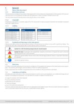
This document is to be kept in the vicinity of the equipment for future reference and explanation of the operation of the device. This document is to be delivered and kept with the equipment in case of change of location and/or user. The most recent issue of this document can be found online, on our website. Modification and partial or complete usage of this PDF document for other purposes as intended are forbidden and breach may lead to legal process. This manual is valid for the following equipment and its variants: Warning and safety notices as well as general notices in this document are...
Open the catalog to page 5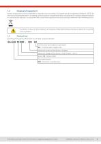
A piece of equipment which is intended for disposal must, according to European laws and regulations (ElektroG, WEEE) be returned to the manufacturer for scrapping, unless the person operating the piece of equipment or another, delegated person is conducting the disposal. Our equipment falls under these regulations and is accordingly marked with the following symbol: The device contains a Lithium battery cell. Disposal of that battery follows the above stated rule or specific local regulations. Decoding of the product description on the label, using an example: © EA Elektro-Automatik in 2022,...
Open the catalog to page 6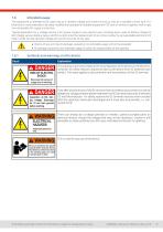
The equipment is intended to be used only as a variable voltage and current source or only as a variable current sink. Furthermore it's only intended to be used installed and operated in suitable equipment (19” rack or similar), together with a rigid, non-retractable AC supply connection. Typical application for a voltage source is DC power supply to any relevant user, including when used as battery charger to test charge various battery types, and for current sinks the replacement of an ohmic resistor by an adjustable electronic DC load in order to load relevant voltage and current sources of...
Open the catalog to page 7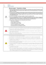
Safety notices • Electrical equipment operation means that some parts accessible on the outside of the device can be under high voltage. Therefore all parts under voltage must be covered during operation! This basically applies to all models. • The DC terminal is isolated from the AC input and not connected to ground internally. Hence there can be dangerous potential between the DC poles and PE, for instance caused by a connected external source application. Due to charged capacitors this could even be true if the DC input or the device are already switched off. • Do not insert any object, particularly...
Open the catalog to page 8
Operator is any natural or legal person who uses the equipment or delegates the usage to a third party, and is responsible during its usage for the safety of the user, other personnel or third parties. The equipment is in industrial operation. Therefore the operators are governed by the legal safety regulations. Alongside the warning and safety notices in this manual the relevant safety, accident prevention and environmental regulations must also be applied. In particular the operator has to • be acquainted with the relevant job safety requirements • identify other possible dangers arising from...
Open the catalog to page 9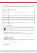
The equipment offers various possibilities for signaling alarm conditions, however, not for danger situations. The signals may be optical (on the display as text or via LED), acoustic (piezo buzzer) or electronic (pin/status output of an analog interface). All alarms will cause the device to switch off the DC input. For details about the different alarms refer to section "3.3. Alarm conditions". The meaning of the signals is as follows: The operator of the device must decide when to check the device for correct functionality, by whom and how often. The when could either be before every use or...
Open the catalog to page 10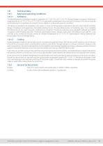
Technical Data Approved operating conditions Ambiance The allowed ambient temperature range for operation is 0 °C (32 °F) to 50 °C (122 °F). During storage or transport, the allowed range extends to -20 °C (-4 °F) to 70 °C (158 °F). In case water condensation occurred due to transport, the device must be acclimatized prior to operation for at least 2 hours, ideally in a place with good air circulation. The device is intended to be operation in dry rooms. It must not be exposed or operated to extreme dust, high air humidity, danger of explosion and aggressive chemicals polluting the air. The operating...
Open the catalog to page 11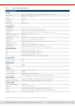
Voltage, Phases Range 1: 110 - 127 V, ±10%, Iph AC (with DC input power derating to 1.2 kW or 1.5 kW) Range 2: 208 - 240 V, ±10%, 1ph AC Overvoltage category <0.05% FS (0 - 100% load, constant input voltage and constant temperature) Line regulation CV <0.01% FS (110 V - 240 V AC +10%, constant load and constant temperature) Stability CV <0.02% FS (during 8 h of operation, after 30 minutes warm-up, at constant input voltage, load and temperature) Temperature coefficient CV <30ppm/°C (after 30 minutes of warm-up) Compensation (remote sense) <5 % U Nominal Load regulation CC <0.1% FS (0 - 100% load,...
Open the catalog to page 12All TPS Elektronik GmbH catalogs and technical brochures
 TO Series
9 Pages
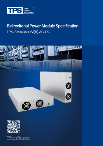 TPS-BM143400SI(R)
4 Pages
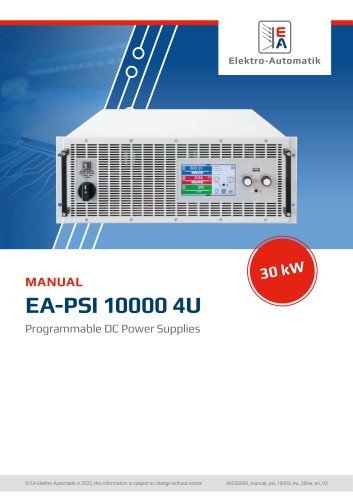 EA-PSI 10000 4U
97 Pages
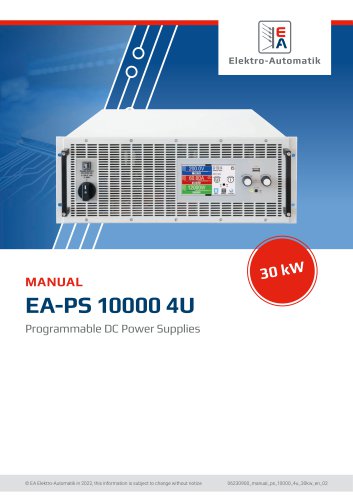 EA-PS 100004U
75 Pages
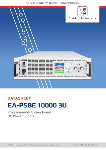 EA-PSBE 10000 3U
15 Pages
 EA-PS 10000 2U
68 Pages
 TPS-MPT36S
2 Pages
 FSP090-ABAN3_spec
8 Pages
 ESD Trolley
2 Pages
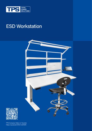 ESD Workstation
4 Pages
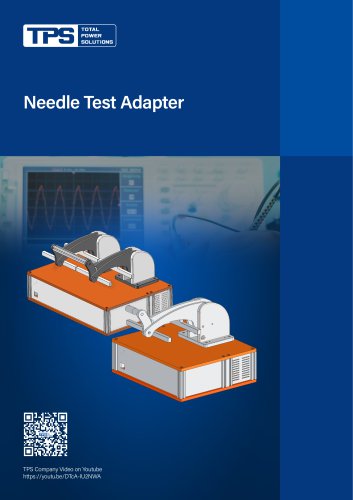 Needle Test Adapter
2 Pages
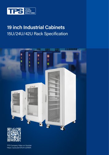 19 inch Industrial Cabinets
5 Pages
 Aluminum Profile Heat Sink
8 Pages
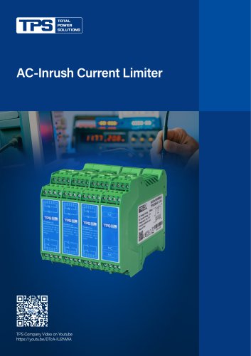 AC-Inrush Current Limiter
3 Pages
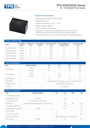 TPS-AWD1023S Series
4 Pages
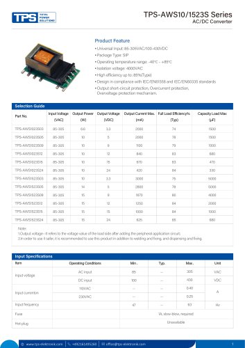 TPS-AWS10/1523S Series
5 Pages
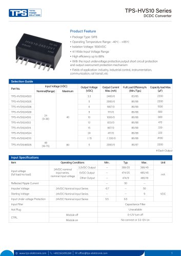 TPS-HVS10 Series
4 Pages
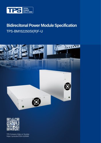 TPS-BM152250SI(R)F-U
4 Pages
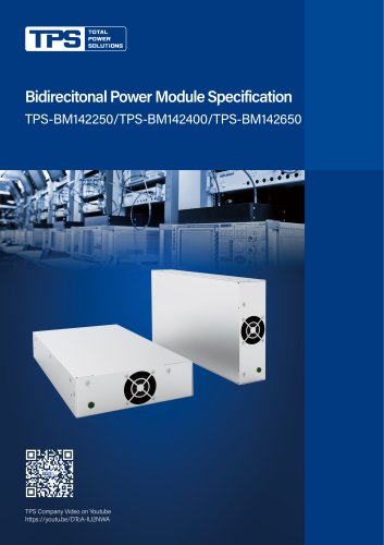 TPS-BM 142250/142400/142650
5 Pages
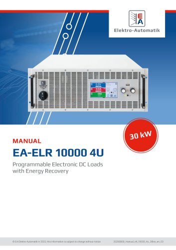 EA-ELR 10000 4U
96 Pages
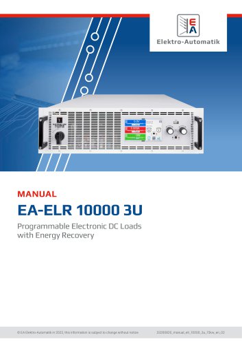 EA-ELR 10000 3U
95 Pages
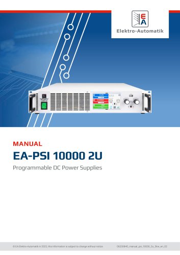 EA-PSI 10000 2U
92 Pages
 EA-PSB 10000 2U
105 Pages
 EA-PS 9000 1U
4 Pages
 EA-PS 2000 B
4 Pages
 EA-PSI 9000 DT
6 Pages
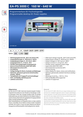 EA-PS 3000C
4 Pages
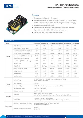 TPS-RPS120S Series
2 Pages
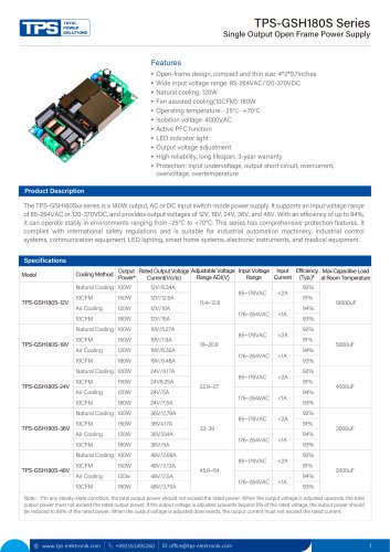 TPS-GSH180S Series
4 Pages
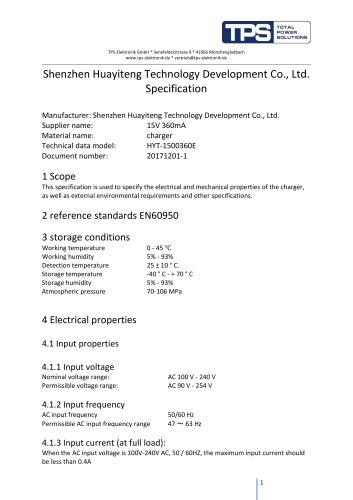 HYT-1500360E
6 Pages
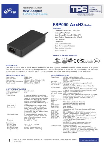 FSP090-AxxN3 Series
4 Pages
 FSP550-50FS
49 Pages
 FSP220-50FGBBI
10 Pages
 FSP300-70PFL(SK)
14 Pages
 FSP300-50UCB
14 Pages
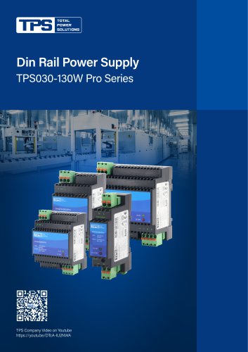 TPS030-130W Pro Series
4 Pages
 TPS100-320W Peak DR+ Series
4 Pages
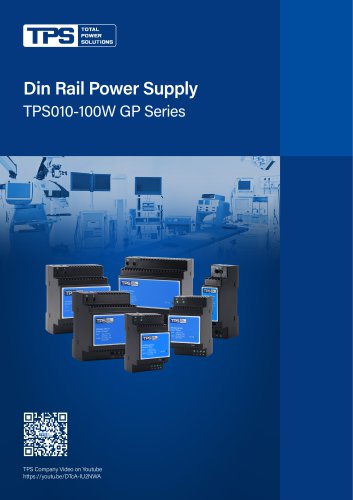 TPS010-100 GP Series
4 Pages


- AC/DC power supply
- Transformer
- Dry transformer
- Metal cart
- CE power supply
- Propeller fan
- Transport trolley
- Air circulation fan
- Floor-mounted cabinet
- Industrial fan
- Single-output power supply
- Air blower
- Power supply for industrial applications
- Door cabinet
- AC fan
- Switched-mode power supply
- Workbench
- Centrifugal blower