BeamBoard
1 /100Pages
BeamBoard
1 /100Pages
Catalog excerpts

User manual Version 1.0 T.P.A. Srl Tecnologie e Prodotti per l’Automazione – Via Carducci, 221 – 20099 Sesto S. Giovanni Phone: +390236527550 – www.tpaspa.it
Open the catalog to page 1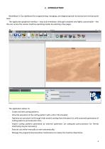
BeamBoard is Tpa dashboard for programming, managing, and diagnosing both horizontal and vertical panel saws. The application graphical interface - easy and immediate, although complete and highly customisable - lets the user access the various machine operating modes by selecting a few pages. - Create and edit cutting patterns; - View the execution of the cutting pattern with a 2D or 3D simulator; - Optimize an execution list (through Ardis motor) starting from the piece list, with automatic generation of cutting patterns and execution lists; - Import cutting patterns generated by external optimizers...
Open the catalog to page 4
The application needs a Tpa hardware key license (there are several license levels, all must be enabled by codes created by a remotely programmable key). Without a Tpa hardware key, the “Demo” mode is enabled by default (please read the paragraph “Demo mode”, chapter “Appendix”). 1.1 SYSTEM REQUIREMENTS The following are the minimum requirements for the computer on which the application will be installed: - Windows 10 OS (application compatible with a 64-bit environment, which we recommend); Dual-core processor (quad-core recommended); Video card with at least 1 GB of dedicated memory and OpenGL...
Open the catalog to page 5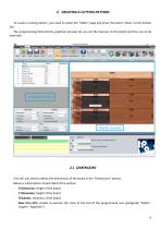
2. CREATING A CUTTING PATTERN To create a cutting pattern, you need to select the “Editor” page and press the button “New” on the button bar. The programming field and the graphical preview let you set the features of the board and the cuts to be executed. 2.1 DIMENSIONS First off, you need to define the dimensions of the board in the “Dimensions” section. Below is a description of each field of the section: - X Dimension: length of the board. Y Dimension: height of the board. Thickness: thickness of the board. Rear trim (HS): enable to execute the trims at the end of the programmed cuts (paragraph...
Open the catalog to page 6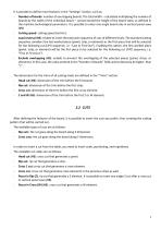
It is possible to define more features in the "Settings" section, such as: - Number of boards: number of overlapping boards. The total width - calculated multiplying the number of boards by the width of the individual board - cannot exceed the height of the board stack, as defined in the machine technological parameters. It is possible to enter one single board only in vertical panel saws (VS). - Cutting speed: cutting speed (m/min). - Load reversal (HS): enable to invert the execution sequence of cuts of different levels. The standard cutting sequence considers the last worked piece (panel,...
Open the catalog to page 7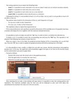
The cutting sequence must respect the following levels: - Level 1: it is possible to insert only head or rip cuts on a board. Head cuts can only be inserted on boards. - Level 2: it is possible to insert only cross cuts on a strip. - Level 3: it is possible to insert only Z cuts on a cross element. - Level 4 (HS): it is possible to insert only W cuts on a Z element. Following this setting, it is not possible to insert a Z or W cut after a rip cut, and it is not possible to insert a W cut after a cross cut. The position value stands for the dimension of the cut, and it depends on its type: - For...
Open the catalog to page 8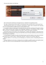
The data input window is the following: After confirming the entered data, the programmed cut is displayed in the graphical preview. The origin of programming is bottom right for horizontal panel saws and bottom left for vertical panel saws. The generated piece (panel, strip, or element) is represented in a darker colour compared to the remaining parts, so to easily identify the available space for eventual additional cuts. It is possible to display the dimensions of the generated piece and of the remaining part through the setting option “Display dimensions (2D)” defined in the setting page...
Open the catalog to page 9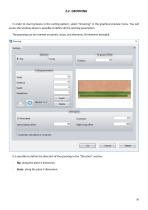
In order to insert grooves in the cutting pattern, select “Grooving” in the graphical preview menu. You will access the window where is possible to define all the working parameters. The grooving can be inserted on panels, strips, and elements, W elements excluded. It is possible to define the direction of the grooving in the “Direction” section: - Rip: along the piece X dimension. Cross: along the piece Y dimension
Open the catalog to page 10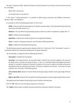
The value “1st groove offset” defines the distance of the first groove from the piece reference point, that will be, accordingly: - Below (with a rip groove). On the right (with a cross groove). In the section “Cutting parameters” it is possible to define groups of grooves with different dimensions, distance, depth, and repetitions. It is possible to enter the following parameters on the screen: - Width: it lets you define the grooving size. During the execution phase, it will automatically calculate how many times the blade needs to run. Distance: it lets you define the gap between grooves,...
Open the catalog to page 11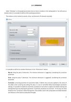
Select “Windows” on the graphical preview menu to insert a window in the cutting pattern. You will access a window where it is possible to define all the working parameters. The window can be inserted on panels, strips, and elements, W elements excluded. It is possible to define the window dimensions in the “Dimensions” section: - Rip-cut: along the piece X dimension. The minimum dimension is suggested, considering the correction parameter. Cross: along the piece Y dimension. The minimum dimension is suggested, considering the correction parameter. Correction: correcting parameter for pneumatic...
Open the catalog to page 12
It is possible to define the position on the piece of the window in the “Position” section. - Right edge: distance of the window from the right reference point. Bottom edge: distance of the window from the bottom reference point. Horizontal centering: it enables the centring of the window along the piece X dimension. It disables the distance from the right reference point. Vertical centering: it enables the centring of the window along the piece Y dimension. It disables the distance from the bottom reference point. The graphical preview represents the window inside the selected piece in yellow....
Open the catalog to page 13All T.P.A. SRL TECNOLOGIE PRODOTTI catalogs and technical brochures


- Panel PC
- Industrial panel PC
- Panel PC with touch screen
- LCD screen
- Industrial monitor
- Automation software solution
- Industrial computer
- Intel® Core™ PC
- Fanless PC
- Intel® Core™ panel PC
- VESA mounting monitor
- HDMI PC
- Box PC
- Windows PC
- Digital I/O
- USB keyboard
- Industrial keyboard
- IO module
- USB monitor
- Keyboard with mechanical keys