TN-17
1 /6Pages

TN-17
1 /6Pages
Catalog excerpts

Worldwide www.tyco-fire.com Contacts Model TN-17 16.8 (K240) K-factor Horizontal Spray Nozzle, Open General Description The TYCO Model TN-17 Horizontal Spray Nozzle having a 16.8 (K240) K-factor is a specialized open nozzle for use in tunnel fire protection deluge systems, providing an improved alternative to traditional designs. With its ability to provide extended coverage, the Model TN-17 Nozzle allows for a single pipe to run the length of a tunnel, compared to traditional designs that use multiple pipes in order to provide sufficient coverage. The Model TN-17 Nozzle is an open nozzle designed to be integrated into a deluge fire protection system. The Model TN-17 Nozzle provides protection of coverage areas up to 16 ft 4 in. x 32 ft 8 in. (5,0 m x 10,0 m) as compared to standard coverage sprinklers often used in tunnel fire protection system designs having a maximum coverage area of 10 ft x 10 ft (3,0 m x 3,0 m). NOTICE The TYCO Model TN-17 Horizontal Spray Nozzle described herein must be installed and maintained in compliance with this document and with the applicable standards recognized by any authorities having jurisdiction. Failure to do so may impair the performance of these devices. The design of individual fixed water spray systems for fire protection can vary considerably, depending on the characteristics and nature of the hazard, the basic purpose of the spraying system, the configuration of the hazard, and wind/draft/ventilation conditions. Because of these variations, the design of fixed water spray systems must only be performed by experienced designers who thoroughly understand the limitations as well as capabilities of such systems. The Tunnel Operator is responsible for maintaining their fire protection system and devices in proper operating condition. Contact the installing contractor or product manufacturer with any questions. Technical Data Approvals Minimum Working Pressure 10 psi (0,7 bar) Maximum Working Pressure 30 psi (2,1 bar) Pipe Thread Connections 3/4 in. NPT or ISO 7-R 3/4 Discharge Coefficient Natural Brass Physical Characteristics Natural Brass Frame ���������������������������������������������������������Brass Deflector Screw �������������������������� Stainless Steel Deflector �����������������������������������������������������Brass Deflector Nut ���������������������������������������������Bronze IMPORTANT Refer to Technical Data Sheet TFP2300 for warnings pertaining to regulatory and health information. Always refer to Technical Data Sheet TFP700 f
Open the catalog to page 1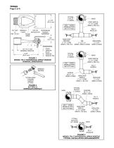
MAIN DROP NIPPLE: 2" x 8" LONG (DN50 x 200 mm) USE 1" (DN25) MINIMUM PIPE AND FITTINGS 3/4" NPT WRENCH TOP OF CENTERLINE or FLATS DEFLECTOR NOZZLE ISO 7-R 3/4 WATERWAY FRAME ARMS 3/4" (19,1 mm) ARM-OVER NIPPLES: 2" x 5" LONG (DN50 x 125 mm) Components: 1 - Frame 2 - Deflector Screw 3 - Deflector 4 - Deflector Nut FIGURE 1 MODEL TN-17 HORIZONTAL SPRAY NOZZLE NOMINAL DIMENSIONS MAIN DROP NIPPLE: 2" x 8" LONG (DN50 x 200 mm) USE 1" (DN25) MINIMUM PIPE AND FITTINGS WRENCH RECESS ELBOW: 90° 2" x 2" (DN50 x DN50) "FITTING SIDE" TOWARD NOZZLE FITTING FIGURE 2 W-TYPE 21 SPRINKLER WRENCH ARM-OVER NIPPLE:...
Open the catalog to page 2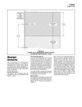
NOZZLES AND FITTINGS SHOWN ENLARGED COVERAGE AREAS ADJACENT COVERAGE AREAS FIGURE 4 MODEL TN-17 HORIZONTAL SPRAY NOZZLE COVERAGE AND SPACING – PLAN Design Criteria The TYCO Model TN-17 K=16.8 Horizontal Spray Nozzle is intended for integration into a water spray, deluge fire protection system designed in accordance with the applicable standards recognized by any authorities having jurisdiction. Nozzle Orientation The Model TN-17 Nozzle must be installed in a horizontal orientation. See Figures 1 and 3. Corrosion Resistance It is recommended that the Tunnel Operator be consulted with respect to...
Open the catalog to page 3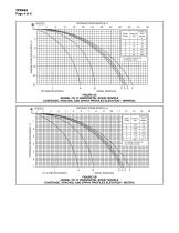
DISTANCE FROM NOZZLE, ft 20 28 32 24 DISTANCE BELOW NOZZLE, ft Distance from Nozzle* ft * UL testing measured at 18 ft below nozzle SPRAY PROFILES FIGURE 5A MODEL TN-17 HORIZONTAL SPRAY NOZZLE COVERAGE, SPACING, AND SPRAY PROFILES ELEVATION – IMPERIAL NOZZLE 1 Spray Profile 1 DISTANCE BELOW NOZZLE, m Distance from Nozzle* m 5,2 * UL testing measured at 5,5 m below nozzle SPRAY PROFILES FIGURE 5B MODEL TN-17 HORIZONTAL SPRAY NOZZLE COVERAGE, SPACING, AND SPRAY PROFILES ELEVATION – METRIC
Open the catalog to page 4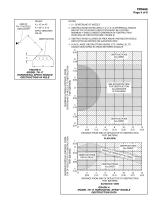
TFP852 Page 5 of 6 RULES: A ≥ 4C or 4D A ≤ 60" (1,5 m) APPLY GREATEST VALUE OBSTRUCTION A NOTES: 1. 0 = CENTERLINE OF NOZZLE 2. OBSTRUCTIONS WITHIN AREA 5'-0" (1,5 m) SPHEREICAL RADIUS BELOW TOP OF NOZZLE DEFLECTOR MUST BE LOCATED MINIMUM 4 TIMES LONGEST DIMENSION OF OBSTRUCTION FROM END OF DEFLECTOR (REF. FIGURE 6) 3. OBSTRUCTIONS ALLOWED IN AREA ABOVE AND BELOW NOZZLE DEFLECTOR AS DEFINED ON ELEVATION VIEW FIGURE 6 MODEL TN-17 HORIZONTAL SPRAY NOZZLE OBSTRUCTION 4X RULE MAXIMUM LATERAL DISTANCE FROM CENTERLINE OF NOZZLE TO OBSTRUCTION FEET (METERS) 4. PLACE LARGE OBSTRUCTIONS (SIGNS, ETC.)...
Open the catalog to page 5
Installation The TYCO Model TN-17 K=16.8 Horizontal Spray Nozzle, as shown in Figures 1 and 2, must be installed in accordance with this section. NOTICE The Model TN-17 Nozzle must be installed in accordance with the pipe dimensions shown in Figure 3. Failure to do so will impair the intended performance of the system. General Instructions The Model TN-17 Nozzle is to be oriented horizontally with the plane created by its two frame arms parallel with the ceiling or parallel with the finished grade, in the case of a non-flat ceiling. Step 1. Ensure all piping components are properly assembled...
Open the catalog to page 6All Total catalogs and technical brochures
 FV-300/BFV-300C
8 Pages
 CV-300B
1 Page
 ESFR-17
8 Pages
 TOTALIT G Ultra
5 Pages
 Air TOTAL
4 Pages
 Total UK brochure 1108
32 Pages