RAPID RESPONSE Model RCP-1 Residential Control Panel

RAPID RESPONSE Model RCP-1 Residential Control Panel
The TYCO RAPID RESPONSE Model RCP-1 Residential Control Panel is designed for controlling water release in residential dry pipe sprinkler systems, suitable for one- and two-family dwellings and mobile homes according to NFPA 13D standards. It includes a pre-wired assembly with a control panel, gauges, and a compressor, featuring a supervised valve system and a 48-hour battery backup.
Installation and maintenance must be performed by qualified personnel in compliance with NFPA standards. Owners are responsible for system maintenance. The panel will not operate if AC power is disconnected and the battery is drained. Electrical and static hazards require precautions during servicing.
The panel is UL Listed for residential dry pipe systems, operating at a maximum water pressure of 175 psi and requiring 120 VAC input voltage. The battery backup provides 48-hour standby and 15-minute alarm/system release. The system includes various circuits for alarms and notifications, with specific ratings for each.
The system maintains air pressure between 10 to 14 psi. In standby, water is blocked until the solenoid valve is activated. The operator interface uses LEDs and keys to display status and control the system. Retesting is required after modifications to ensure proper operation.
The equipment operates within 32°F to 120°F and up to 93% humidity. The manifold assembly is constructed of brass and bronze. The system's trip ratio is calculated based on static water supply pressure.
Figures illustrate the assembly and components of the Model RCP-1, including the manifold assembly and operator interface. Graph A shows the nominal pressure loss versus flow rate for the control panel.
- Verify no fire condition exists.
- Close Main Control Valve to prevent water flow.
- Acknowledge notification by pressing ACCEPT SIGNAL KEY to silence alert.
- Identify and correct cause (e.g., power loss, low battery, high air pressure).
- Reset system promptly.
- Confirm fire condition and take action (evacuate, call fire department).
- After extinguishing fire, reset system.
- If no fire, silence alarms by pressing ACCEPT SIGNAL KEY and SIGNAL SILENCE KEY.
- Accept all abnormal statuses using ACCEPT SIGNAL KEY.
- Silence alarms with SIGNAL SILENCE KEY.
- Close Main Control Valve and turn off Air Compressor.
- Open Drain and Flow Test Valves, replace sprinklers, and allow system to drain.
- Turn on Air Compressor to reestablish air pressure (10-14 psi).
- Reset Electronic Control with SYSTEM RESET KEY.
- Open Main Control Valve slowly to clear supervisory signal.
- Install Model RCP-1 Panel per NFPA standards and local authority requirements.
- Surface or recessed mounting options available; avoid freezing areas.
- Field connections include water supply, system riser, drain line, and electrical.
- Remove resistors only when instructed.
- Ensure no wiring contacts CPVC pipes to prevent damage.
- Optional for waterflow alarms; follow specific wiring guidelines.
- Maximum alarm current is 1A; distance varies by wire gauge.
- Optional for central control monitoring; follow specific wiring guidelines.
- Relays are single pole, double throw; set jumpers as needed.
- Connect batteries per instructions; leave one connection unconnected initially.
- Connect to a dedicated branch circuit per local codes.
- Perform inspections/tests per NFPA and local requirements.
- Notify authorities before and after system maintenance.
- Verify air pressure and AC power indicators.
- Perform lamp test and trip test as outlined.
- Verify pre-programming by checking MODE positions.
- Correct any discrepancies and restore settings.
- Warranty details available online.
- Contact distributor for orders, specifying product name and part number.
Catalog excerpts

Worldwide Contacts RAPID RESPONSE Model RCP-1 Residential Control Panel 1 or 1-1/2 Inch (DN25 or DN40), 175 psi (12,1 bar) IMPORTANT Refer to Technical Data Sheet TFP2300 for warnings pertaining to regulatory and health information. General Description The TYCO RAPID RESPONSE Model RCP-1 Residential Control Panel is an integrated valve manifold, air pressure, and electronic control package for controlling the release of water into residential dry pipe sprinkler systems. The Model RCP-1 Panel is intended for use in one- and two- family dwellings and mobile homes per NFPA 13D when used with residential sprinklers that have been listed for use in residential dry pipe sprinkler systems. The Model RCP-1 Panel incorporates the Listed Model 4004R Household Fire Warning Unit Subassembly installed within the Model RCP-1 cabinet. The Model RCP-1 Panel includes the following features: • Pre-wired assembly containing preprogrammed control panel, system performance gauges, and an enclosed compressor • Pre-engineered riser design • Supervised system valve system • Provision to trip test system without having water flow into the system. • High pressure supervision for indication of a false trip or failure of the automatic air supply cut-out switch • Dry contacts for remote connection (dial-up systems or additional monitoring, for example) • 48-hour battery backup Warnings General The RAPID RESPONSE Residential Dry Pipe System described herein must be installed and maintained by qualified personnel in compliance with this document, and with the applicable standards of the NATIONAL FIRE PROTECTION ASSOCIATION, in addition to the requirements of any other authorities having jurisdiction. Failure to do so may impair the performance of this device. Owner Responsibility Owners are responsible for maintaining their fire protection system and devices in proper operating condition and in compliance with all applicable standards and requirements. Contact the installing contractor or product manufacturer with any questions. Do NOT Disconnect Batteries or Turn Off AC Power to Quiet Unwanted Alarms. The Model RCP-1 Panel will not operate (that is, release water or energize alarms) if AC power is not connected, has failed, or has been interrupted for any reason AND the battery is disconnected, drained, or improperly connected. Household Fire Alarm System The use of an automatic sprinkler system does not allow for omission of a “Household Fire Alarm System” installed per NFPA 72. The Model RCP-1 Panel is not intended to be used as part of a “Household Fire Alarm System”. Electrical Hazard Disconnect electrical field power when making any internal adjustments or repairs. Failure to do so may result in personal injury. Servicing should be performed by qualified personnel. Static Hazard Static electricity can damage components. Therefore, qualified personnel must be grounded before opening components, installing components, and prior to installation. Keep components wrapped in anti-static material at all times. Radio Frequency Energy This equipment generates, uses, and can radiate radio frequency energy, and if not installed and used in accordance with this technical data sheet, may cause interference to radio communications. This equipment has been tested and found to comply with the limits for a Class A computing device pursuant to Subpart J of Part 15 of FCC Rules, that are designed to provide reasonable protection against such interference when operated in a commercial environment. However, operation of this equipment in a residential area may cause interference, in which case the user, at their own expense, will be required to take whatever measure may be required to correct the interference. System Re-Acceptance Test To ensure proper operation, this product must be retested by qualified personnel in accordance with the Care and Maintenance section after any modification, repair, or adjustment. Retesting is required to assure that the system is operating as intended.
Open the catalog to page 1
Technical Data Approvals The Model RCP-1 Residential Control Panel is UL Listed for use in residential dry pipe sprinkler systems installed in one and two-family dwellings and mobile homes per NFPA 13D when installed in accordance with this document. The Model 4004R Household Fire Warning Unit Subassembly (Electronic Control) installed within the Model RCP-1 cabinet is UL and C-UL Listed. Maximum Water Pressure 175 psi (12,1 bar) Friction Loss Refer to Graph A Input Voltage 120 VAC, 60 Hz, 4 A Battery Backup Two 8.0 amp-hour 12 VDC batteries in series provides a minimum of 48 hours of standby...
Open the catalog to page 2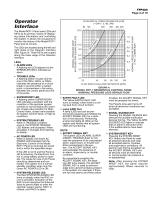
Operator Interface FLOW RATE IN LITRES PER MINUTE (LPM) (1 GPM = 3,785 LPM) 80 100 200 300 400 500 • ALARM LEDs A flashing red LED adjacent to the SPRINKLER (IDC1) indicates an alarm. • TROUBLE LEDs A flashing yellow Trouble LED for one of the IDCs, NACs, or RACs indicates the presence of a circuit break or ground within a system point, or somewhere in the wiring between the control panel and one of its points. • SUPERVISORY LED A flashing yellow SUPERVISORY LED indicates a problem with the condition of the sprinkler system controls or normal status (for example, closed valve position for Main...
Open the catalog to page 3
OPERATOR INTERFACE WINDOW ELECTRONIC CONTROL BACKUP BATTERIES OPERATOR INTERFACE AIR PRESSURE CONTROL DISCONNECT "ON/OFF" SWITCH OUTLET CONNECTION TO DRY PIPE FIRE PROTECTION SYSTEM SYSTEM AIR SUPPLY PRESSURE GAUGE 50" (1270 mm) SYSTEM WATER SUPPLY PRESSURE GAUGE MANIFOLD ASSEMBLY HINGED LOCKING PANEL DOOR AIR PRESSURE CONTROL MOUNTING BRACKETS LEFT SIDE ENCLOSURE (PANEL DOOR NOT SHOWN) SYSTEM WATER SUPPLY * CONNECTION SYSTEM DRAIN CONNECTION * Always consult local jurisdictions for water supply criteria and requirements. FIGURE 1 MODEL RCP-1 RESIDENTIAL CONTROL PANEL ASSEMBLY
Open the catalog to page 4
TFP480 Page 5 of 10 DRY PIPE FIRE PROTECTION SYSTEM OUTLET CONNECTION (1 or 1-1/2 INCH NPT) TUBING TO SYSTEM AIR SUPPLY PRESSURE GAUGE PRESSURE SWITCH, POTTER ELECTRIC PS10-2: INCREASE 16±1 PSI DECREASE 8±1 PSI SYSTEM CONTROL VALVE (NORMALLY OPEN) SPRING LOADED CHECK VALVE AIR COMPRESSOR SWITCH CUT-IN: 10 PSI CUT-OUT: 14 PSI FLOW AIR COMPRESSOR SWITCH TO AIR COMPRESSOR WIRING HARNESS SPRING LOADED CHECK VALVE SOLENOID VALVE (NORMALLY CLOSED UNTIL ENERGIZED) TUBING TO SYSTEM WATER SUPPLY PRESSURE GAUGE DRAIN VALVE (NORMALLY CLOSED) FLOW TEST VALVE (NORMALLY CLOSED) MAIN CONTROL VALVE (NORMALLY...
Open the catalog to page 5All Total catalogs and technical brochures
 FV-300/BFV-300C
8 Pages
 TN-17
TN-176 Pages
 CV-300B
1 Page
 ESFR-17
8 Pages
 TOTALIT G Ultra
5 Pages
 Air TOTAL
4 Pages
 Total UK brochure 1108
32 Pages