Model AV-1-300 Alarm Check Valve, 300 psi (20,7 bar) 2-1/2, 4, 6 & 8 Inch (DN65, DN100, DN150 & DN200) Vertical or Horizontal* Installation
1 /20Pages

Model AV-1-300 Alarm Check Valve, 300 psi (20,7 bar) 2-1/2, 4, 6 & 8 Inch (DN65, DN100, DN150 & DN200) Vertical or Horizontal* Installation
1 /20Pages
Catalog excerpts

Worldwide Contacts tuca m Fire Protection Products General Description The TYCO Model AV-1-300 Alarm Check Valves are divided seat ring, rubber-faced clapper, waterflow alarm check valves that are intended for use in wet pipe (automatic sprinkler) fire protection systems. They may be installed vertically or horizontally1, and they are designed to automatically actuate electric and/or hydraulic alarms when there is a steady flow of water into the system that is equivalent to the discharge rate of one or more sprinklers. A separately ordered Model RC-1 Retard Chamber (Ref. Technical Data Sheet TFP920) is required for installations subject to variable pressures. It is used to help prevent false alarms associated with pressure variations in public water supplies. The AV-1-300 Alarm Check Valve Trim includes pressure gauges to monitor system pressure conditions, a bypass check valve, a main drain valve, and an alarm test valve. The bypass check valve reduces the possibility of false alarms by permitting slow as well as small transient increases in water supply pressure to be passed through to the system without opening the waterway clapper. The TYCO Model AV-1-300 Alarm Check Valves described herein must be installed and maintained in compliance with this document, as well as with the applicable standards of the National Fire Protection Association (NFPA), in addition to the standards of any authorities having jurisdiction. Failure to do so may impair the integrity of these devices. The owner is responsible for maintaining their fire protection system and devices in proper operating condition. Contact the installing contractor or product manufacturer with any questions. Technical Data Approvals UL and C-UL Listed FM Approved Working Water Pressure Range 20 to 300 psi (1,4 to 20,7 bar) Friction Loss Refer to Graph A. End Connections Groove x Groove Flange x Groove Flange x Flange Refer to Table A for size applicability Weights Refer to Table A. Physical Characteristics The body is ductile iron, the hand-hole cover is ductile iron, and the seat ring is bronze. The clapper for the 2-1/2 inch (DN65) valve size is stainless steel. The clapper for the larger valve sizes is ductile iron. All valve sizes utilize an EPDM clapper facing. Flanged connections are available drilled per ANSI, ISO, AS, and JIS specifications as detailed in Table B. Threaded port connections for the AV-1-300 Valves are available NPT threaded or threaded per ISO 7-1 as detailed in the Ordering Procedure section. Valves with NPT threaded ports will readily accept the trim arrangements detailed in Figures 4 through 6. ®c®<a> APPROVED
Open the catalog to page 1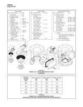
REPLACEMENT PARTS NO. DESCRIPTION P/N NOTES: 1. F x F valve shown for reference; components for G x G and F x G valves are shared. 2. NR: Not Replaceable 3. CH: Common Hardware Nominal Valve Size Inches (DN) TABLE A MODEL AV-1-300 ALARM CHECK VALVE AVAILABLE VALVE END CONNECTIONS AND VALVE WEIGHTS
Open the catalog to page 2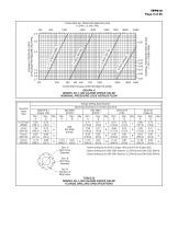
Nominal Valve Size Dim. A Bolt Circle Diameter Dim. B Bolt Hole Diameter Qty. N Number of Bolt Holes 1 Same drilling as for B16.5 (Class 150) and B16.42 (Class 250). 2 Same drilling as for BS 4504 Section 3.2 (PN10) and DIN 2532 (PN10). 3 Same drilling as for BS 4504 Section 3.2 (PN16) and DIN 2532 (PN16).
Open the catalog to page 3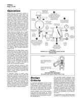
Operation When the fire protection system is initially pressurized, water flows into the system until the water supply and system pressure become equalized, and the torsion Spring closes the Waterway Clapper in the Alarm Check Valve. Once the pressures stabilize, the Alarm Check Valve is in service and the centrally located groove in the Seat Ring is sealed. Consequently, with the Alarm Check Valve set for service, there is no flow through the alarm port to the alarm devices (i.e., water motor alarm and/or pressure alarm switch). When there is a steady flow of water into the sprinkler system...
Open the catalog to page 4
that the flow out of the system through the test valve or a single sprinkler is very small relative to the flow that can be passed through the valve. This difference increases with valve size. If the system were free of trapped air, flow in would equal flow out and the Waterway Clapper would always stabilize at some open position (as needed to accommodate the required flow). With trapped air in the system, however, the Waterway Clapper first opens wider since the system initially demands greater flow until the air pockets are compressed (back to nearly the supply pressure), and then it will tend...
Open the catalog to page 5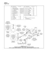
1 300 psi/ 2000 kPa Water Pressure Gauge . . 2 2 1/4" Gauge Test Valve . .2 3 1/2" Swing Check Valve .2 8 External By-Pass Tube . . 1 NOTES: 1. All Fittings and Nipples are galvanized (Standard Order). 2. CH: Common Hardware.
Open the catalog to page 6
1 300 psi/ 2000 kPa Water Pressure Gauge . . 2 2 1/4" Gauge Test Valve . .2 3 1/2" Swing Check Valve . 2 27 Select Nipple per Table . . 2 CH 28 Select Nipple per Table . . 2 CH NOTES: 1. Install subassemblies in alphabetical order. 2. All Fittings and Nipples are galvanized (Standard Order). 3. CH: Common Hardware. LOCATION FOR OPTIONAL ELECTRICALLY SUPERVISED N.O. ALARM CONTROL VALVE
Open the catalog to page 7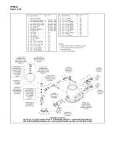
1/2 INCH NPT CONNECTION FOR WATERFLOW PRESSURE ALARM SWITCH NOTES: 1. Install subassemblies in alphabetical order. 2. All Fittings and Nipples are galvanized (Standard Order). 3. CH: Common Hardware. 3/4 INCH NPT CONNECTION FOR WATER MOTOR ALARM 1/2 INCH NPT CONNECTION FOR WATERFLOW PRESSURE ALARM SWITCH LOCATION FOR OPTIONAL ELECTRICALLY SUPERVISED N.O. ALARM CONTROL VALVE ALARM TEST VALVE (NORMALLY CLOSED) 3/4 INCH NPT CONNECTION FOR WATER MOTOR ALARM MODEL RC-1 RETARD CHAMBER ORDERED SEPARATELY (FOR VARIABLE PRESSURE SYSTEMS) 15 20 LOCATION FOR OPTIONAL ELECTRICALLY SUPERVISED N.O. ALARM CONTROL...
Open the catalog to page 8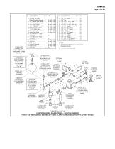
NOTES: 1. All Fittings and Nipples are galvanized (Standard Order). 2. CH: Common Hardware. LOCATION FOR OPTIONAL ELECTRICALLY SUPERVISED N.O. ALARM CONTROL VALVE ORDERED SEPARATELY (FOR VARIABLE PRESSURE SYSTEMS) 1 300 psi/ 2000 kPa Water Pressure Gauge . .2 92-343-1-005 8 External By-Pass Tube . . 1 92-304-1-017
Open the catalog to page 9All Total catalogs and technical brochures
 FV-300/BFV-300C
8 Pages
 TN-17
TN-176 Pages
 CV-300B
1 Page
 ESFR-17
8 Pages
 TOTALIT G Ultra
5 Pages
 Air TOTAL
4 Pages
 Total UK brochure 1108
32 Pages